


12.
13.
14.
15.
16.
17.
16.
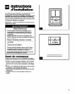
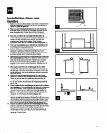
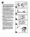
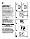
Apply window gasket (G). Measure from right inside
edge of window frame to left inside edge. Then cut the
window gasket, with square ends, to fit. Raise window
sash slightly and place gasket over the top mounting
channel and top edge of filler boards. See Figure 14.
Make sure filler boards are as far forward (toward
inside room) in window channels as possible.
Insert foam blocks (f-f). Measure the distance between
the filler board and the back window channel edge. Cut
foam blocks W (6 mm) wider than measurement. Insert
foam blocks into window channels - behind filler boards.
See Figure 15.
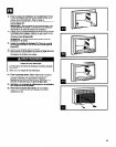
Fasten cabinet to window sill. Lower window sash firmly
onto cabinet. Place a carpenter’s level inside the cabinet
and make sure cabinet is level side-to-side. Then drill
starter holes into the cabinet base and the window sill.
Use round-head wood screws (I) to fasten cabinet to
window sill. See Figure 16.
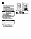
Make sure cabinet has proper outward slope. Place
carpenter’s level in the right side of the cabinet. There
should be a 34 bubble tilt (W [6 mm]) titt toward the
outside. Repeat for left side of cabinet. See Figure 17.
Attach 2%’ (64 mm) seal strip (J) to inside of cabinet.
Make sure the seal strip is flush with the front edge of the
cabinet. This seal strip provides a seal between the air
conditioner base and the cabinet.
Assemble the outside support. Attach the vertical
supports (K) to the angle supports (L). Use the round-head
bolts (M), flat washers (N), lock washers (0) and the nuts
(P) for attachments. Then attach these supports to the
bottom of the cabinet, but DO NOT tighten the botts at this
time.
Attach the wall rail (Cl) the bottom of the supports, and
slide the support assembly toward the house until the wall
rail presses firmly against the wall. See Figure 16.
Now tighten all bolts. Tighten angled support bolts last
so wall rail fits tightly against the house.
NOTE: If your house is constructed of materials that could
be damaged by the wall rail, fasten a board between the
wall rail and the house.
12.
13.
14.
15.
16.
17.
16.
Colocar la empaquetadura de la ventana (G). Medir
desde el borde interior derecho del marco de la ventana al
borde interior izquierdo. Luego cortar la empaquetadura
de la ventana con 10s extremes cuadrados para que calce.
Levantar levemente la hoja de la ventana y colocar la
empaquetadura sobre la canaleta de montaje superior y
en las tablas de relleno del borde superior. Ver Flgura 14.
Asegurarse de que las tablas de relleno eot&r tan
adelante (hacia adentro de la habitation) en las
canaletas de la ventana corno sea poslble.
Inserter for bloques de espuma (H). Medir la distancia
entre la tabla de relleno y el borde de la canaleta trasera
de la ventana. Cortar bloques de espuma 6 mm (W) m&s
anchos que la medida. lnsertar los bloques de espuma
dentro de las canaletas de la ventana detras de las tablas
de relleno. Ver Figura 15.
Instalar la caja meMica en la batiente ds la ventana.
Bajar la hoja de la ventana firmemente hasta la caja
metalica. Colocar un nivel de carpintero dentro de la caja
met&a y asegurarse de que la caja esta nivelada de un
lado al otro. Luego taladrar orificios guia en la base de la
caja metalica y en la batiente de la ventana. Usar 10s
tornillos de madera de cabeza redonda (I) para sujetar la
caja metalica a la batiente de la ventana. Ver Figura 16.
Asegurese de que la caja metilica tenga una
inclination hacia afuera decuada. Colocar el nivel de
carpintero en el lado derecho de la caja met&a. Debe
tener una inclinacidn hacia afuera de aproximadarnente
media burbuja (6 mm [WJ). Repetir para el lado izquierdo
de la caja metalica. Ver Figura 17.
lnstalar la clnta obturadora de 64 mm (2%‘) (J) en la
parte interior de la caja mstilica. Asegurarse de que la
cinta obturadora este al ras con el borde delantero de la
caja rnetalica. Esta cinta obturadora se coloca entre la
base del acondicionador de aire y la caja met&a.
Montaje del soporte exterior. Unir 10s soportes verticales
(K) a 10s soportes angulares (L). Usar 10s pemos de
cabeza redonda (M), las arandelas planas (N), las
arandelas de seguridad (0) y las tuercas (P) coma
sujeciones. Luego instalar estos soportes en la pafte
inferior de la caja metalica, pero NO apretar 10s pemos en
este momento.
lnstalar el travesaiio de la pared (Q) en la parte inferior
de 10s soportes y deslizar el conjunto del soporte contra la
pared de la casa hasta que el travesaiio descanse
firmemente contra la pared. Ver Figure 18.
Ahora apretar todos 10s pemos. Apretar al final 10s
pernos del soporte angular para que el travesaiio de la
pared ajuste firmemente contra la pared de la casa.
NOTA: Si su casa esta construida de materiales que
pueden dafiarse al instalar el travesaiio de la pared,
instalar una tabla entre el travesaho y la pared de la casa.
16