


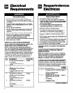


Window installation
1.
2.
3.
4.
5.
6.
7.
6.
9.
10.
11.
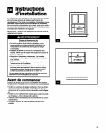
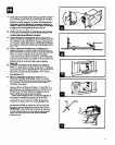
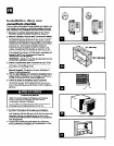
Remove the ground wire and screw from the front of
the unit base. Save grounding screw for reattachment in
Step 22. See Figure 9.
Attach ?& (10 mm) seal strip (A) to bottom of both
side mounting brackets (sides with screw holes). Cut
strips to length and save extra for use later.
Attach side mounting brackets (B) to cabinet. Place
side mounting brackets on cabinet so bent edge is toward
front of cabinet. Attach each with hex-head metal
screws (C).
Slide unit out of cabinet. Grasp handle and slide unit
straight out of cabinet. Place unit on cardboard to protect
your floor.
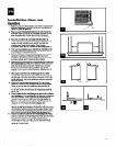
Place empty cabinet in window. Lower window sash to
hold cabinet in place. Make sure the cabinet is centered
in the window opening.
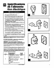
Determine proper size for filler board (E). Measure the
distance from the right edge of the cabinet to the inside of
the right window channel (see Figure 10). Then add l/g
(3 mm) to that measurement. Repeat for left side.
Cut filler board (E) to size. Cut both edges of the filler
board to the proper size. Cut in from the outside edges.
The outside edges should have screw holes in them.
Apply ?4’ (10 mm) seal strip (left over from Step 3) to
the filler boards. Apply seal strips to the bottom front
and outside front edges of the filler boards. The top seal
strip goes on the back side of the filler boards. See
Figure 11.
Attach left filler board to cabinet. Pull cabinet part way
out of the window. Then attach the left filler board to the
front of the left side mounting bracket. Use %” (10 mm)
round-head metal screws (F). See Flgure 12.
Position left filler board in window channel. Place
cabinet back into window. Make sure left filler board sits
lightly against the window channel. See Figure 13.
Attach right filler board to cabinet. Insert right filler
board into right window channel. Push filler board against
right side mounting bracket and attach it with W” (10 mm)
round-head metal screws.
lnstalacih en la ventana
1.
2.
3.
4.
5.
6.
7.
6.
9.
10.
11.
Sacar el tornillo y el alambre de puesta a tlerra de la
parte delantera de la base del acondiclonador.
Consenrar el tornillo de puesta a tiena para volver a
colocarlo en el Paso 22. Ver Figura 9.
Colocar la cinta obturadora de 10 mm (‘n’) (A) en la
parte inferior y en ambos soportes de montaje lateral
(lados con los agujeros de tornlllos). Cortar las tiras a
la medida y guardar el sobrante para usarlo
posteriormente.
lnstalar en la caja metilica lot soporks de rnontaje
lateral (B). Colocar 10s soportes de montaje lateral en la
caja metalica de modo que el borde curve quede hacia el
frente de la caja metalica. lnstalar cada uno con tomillos
para metal de cabeza hexagonal (C).
Deslizar el acondicionador de aire fuera de la caja
metilica. Tirar de la manija derecho hacia afuera de la
caja. Colocar la unidad sobre un pedazo de carton para
proteger el revestimiento de su piso.
Colocar la ca)a met~lica vacia en la ventana Bajar la
hoja de la ventana para sujetar la caja metalica en su
lugar. Asegurarse de que la caja metaliia este en el
centro de la abertura de la ventana.
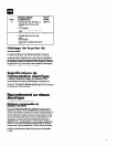
Determinar el tamaiio adecuado para la tabla ds
relleno (E). Medir la distancia desde el horde derecho de
la caja metalica hasta el interior de la canaleta derecha
de la ventana (ver Figure 10). Luego agregar 3 mm (W)
a esa medida. Repetir para el lado izquierdo.
Cortar la tabla de relleno (E) al tamaiio deseado.
Cortar ambos bordes de la tabla de relleno al tamafio
adecuado. Cortar desde 10s bordes exteriores. Los
bordes exteriores deben tener agujeros para tornillos.
Aplicar cinta obturadora de 10 mm (96’) (el restante
del Paso 3) a las tablas de relleno. Aplicar las tiras
obturadoras a la parte delantera inferior y a 10s bordes
delanteros exteriores de las tablas de relleno. La cinta
obturadora superior se coloca en la parte de atrb de las
tablas de relleno. Ver Figura 11.
Instalar la tabla de relleno izquierda en la caja
metilica. Tirar la caja met&a un poco hacia afuera de
la ventana. Luego instalar la tabla de relleno izquierda a
la parte delantera del soporte de montaje lateral
izquierdo. Usar tornillos para metal de cabeza redonda de
10 mm (sh’) (F). Ver Figura 12.
Colocar la tabla de relleno lzqulerda en la canalets de
la ventana Volver a colocar la caja metalica en la
ventana. Asegurarse de que la tabla de relleno izquierda
descansa fim-remente contra la canaleta de la ventana.
Ver Figure 13.
lnstalar la tabla de relleno derecha en la caja meMica.
lnsertar la tabla de relleno derecha en la canaleta
derecha de la ventana. Empujar la tabla de relleno contra
el soporte de montaje lateral derecho y sujetarla con 10s
tornillos de metal de cabeza redonda de 10 mm (9%“).
16