


9
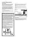
Water Heater Location
□ Centrally located with the water piping system.
□ The fl ooring beneath the water heater must be able
to support the weight of the water heater when fi lled
with water.
□ Located indoors and in a vertical position. Protected
from freezing temperatures.
□ Provisions made to protect the area from water
dam age. Metal drain pan installed and piped to an
adequate drain.
□ Suffi cient room to service the water heater.
□ The site location must be free from any corrosive
elements in the atmosphere such as sulfur, fl uorine,
and chlorine. These elements are found in aero-
sol sprays, detergents, bleaches, cleaning solvents,
air fresheners, paint, and varnish removers, refriger-
ants, and many other commercial and household
products.
INSTALLATION CHECKLIST
Water System Piping
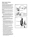
□ Temperature and pressure relief valve properly
installed with a discharge pipe run to an adequate
drain and protected from freezing (See Figure 3).
□ All piping properly installed and free of leaks.
□ Suitable metal drain pan lines installed and piped to
an adequate drain (See Figure 3).
□ Heater completely fi lled with water (See Figure 3).
□ Closed system pressure buildup precautions installed
(See “Closed System/Thermal Expansion” section).
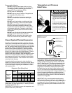
□ Mixing valve (when applicable) installed per manufac-
turer’s instructions (see Figure 4).
Electrical Connections
□ Wiring and connections comply with all applicable
codes.
□ Water heater and electrical supply are properly
grounded.
□ Proper overload fuse or circuit breaker protection
installed.
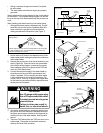
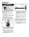
6. Connect the black power wire from the home’s electri-
cal service to the heater’s TWO black wires and
secure with the appropriate size wire nut. When you
are done, you will have THREE black wires under
one wire nut.
7. Locate and connect the remaining power wire (usu-
ally red, but in your home this wire may be some other
color) from the home’s electrical service to the water
heater’s TWO red wires and secure with the appro
priate size wire nut. When you are done, you will have
THREE red wires under one wire nut (depending on
the actual color of your home’s electric wiring).
8. Replace the junction box cover and secure with the
screw removed in step 2.
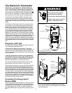
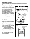
9. Do not remove the Smart Grid cover from the Smart
Grid connector (Figure 8A) unless this feature is be-
ing used (see the “Smart Grid Technology” section
this manual).
10. Insure that the water heater is completely full of water.
Proceed to water heater start up in the “Operating
Your Water Heater” section of this manual.