


7
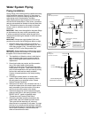
The Temperature & Pressure Relief Valve:
• Must be connected to an adequate discharge line.
• Must not be in contact with any electrical part.
• Must not be rated higher than the working pressure
shown on the data plate of the water heater.
The Discharge Line:
• Must not be smaller than the pipe size of the relief
valve or have any reducing coupling installed in the
discharge line.
• Must not be capped, blocked, plugged, or contain
any valve between the relief valve and the end of
the discharge line.
• Must terminate a maximum of six inches above a
fl oor drain or external to the building. In cold climates,
it is recommended that the discharge pipe be termi-
nated at an adequate drain inside the building.
• Must be capable of withstanding 250° F (121°
C)
without distortion.
• Must be installed to allow complete drainage of
both the valve and discharge line.
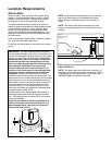
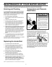
T&P Relief Valve and Pipe Insulation:
1. Locate the temperature and pressure relief valve on
the water heater (also known as a T&P Relief Valve,
(Figure 6).
2. Locate the slit running the length of the insulation.
3 Spread this slit open and slip it up under the T&P
Relief Valve (See Figure 6). Apply gentle pressure to
the insulation to ensure it is fully seated on the T&P
Relief Valve. Once sealed, secure the insulation with
a section of duct tape, electrical tape, or equivalent.
IMPORTANT: The insulation or tape must not block
the discharge opening or hinder access to the manual
relief lever. Ensure a discharge pipe is installed into
the T&P valve discharge opening per the instructions
manual.
4. Locate the hot water (outlet) & cold water (inlet) pipes
to the water heater.
5. Locate the slit running the length of a section of pipe
insulation.
6. Spread the slit open and slip the insulation over
the cold water (inlet) pipe. Apply gentle pressure
along the length of the insulation to ensure it is fully
seated around the pipe. Also ensure that the base of
insulation is flush with the water heater. Once seated,
secure the insulation with duct tape, electrical tape, or
equivalent.
7. Repeat steps 5 through 6 for the hot water (outlet)
pipe.
8. Add additional sections of pipe insulation as needed.
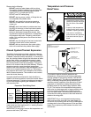
Solar Installation
If this water heater is used as a solar storage heater or
as a backup for the solar system, the water supply
temperatures to the water heater tank may be in excess
of 120° F (48.8° C). A mixing valve or other temperature
limiting valve must be installed in the water supply line to
limit the supply temperature to 120° F (48.8° C).
Note: Solar water heating systems can often supply water
with temperatures exceeding 180° F (82.2° C) and may
result in water heater malfunction.
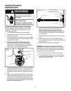
Electrical Requirements
Electric Shock Hazard
Disconnect power before
servicing.
Replace all parts and panels
before operating.
Failure to do so can result in
death or electric shock.
WARNING
Fire Hazard
Use 10 gauge solid copper wire.
Use a UL approved strain relief.
Connect ground wire to green
ground screw.
Failure to do so can result in
death, fire, or electrical shock.
WARNING
If you lack the necessary skills required to properly
install the electrical wiring to this water heater, do not
proceed, but have a qualifi ed electrician perform the
installation.
When making the electrical connections, always make
sure:
• The electrical supply has the proper overload fuse
or circuit breaker protection.
• Wire sizes and connections comply with all
applicable codes.
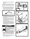
T&P Relief Valve Insulation
Manual Relief Lever
T&P Relief Valve
T&P Relief Valve
Drain Line
Figure 6
Temperature and Pressure
Relief Valve Installation