


8
• Wiring is enclosed in approved conduit (if required
by local codes).
• The water heater and electrical supply are properly
grounded.
Always reference the wiring diagram for the correct electri-
cal connection. The complete wiring diagram can also be
found on the top of the water heater near the junction box
cover.
When installing the electrical wiring to the water heater
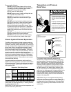
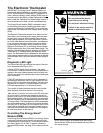
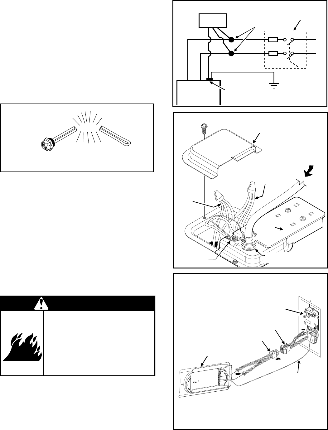
• Although this water heater is equipped with “Dry-fi re”
protection, be sure the tank is completely fi lled with
water, and all air is purged from the tank before
making any electrical connections (See Figure 7).
NOTE: Applying electrical power to elements that are not submerged
in water will destroy them. The manufacturer will not warranty any
elements damaged in this manner.
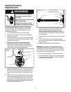
Figure 7
Heating Element
Bang
Energy Smart®
Module (ESM)
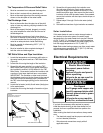
Figure 8B
Electronic Thermostat (ET)
Electronic
Thermostat (ET)
Wiring Harness
( Junction Box )
Wiring Harness
( ET to ESM )
Ground Wire
( Attached To T-Stat Bracket Screw )
Figure 8A
Junction Box
Junction Box Cover
Red Wires
(3)
Black Wires
(3)
Ground Wires
Smart Grid
Cover
1/2” Conduit
Connection
From Home
Electrical Service
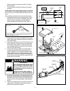
Figure 8
Wiring Diagram
Circuit
Breaker
L1
L2
To 240v
1 Phase
Power
supply
Electrical
Service ground
Ring Terminal
at Ground
Screw
Red
Black
Approved
Connectors
Water Heater
Smart Grid
Wire Harness
Black
Red
Green
Fire Hazard
Use 10 gauge solid copper wire.
Use a UL approved strain relief.
Connect ground wire to green
ground screw.
Failure to do so can result in
death, fire, or electrical shock.
WARNING
1. Check and turn off power to the electrical wiring of the
water heater before making any electrical connections
to the water heater.
2. Remove the junction box cover that is secured by one
screw (Figure 8A). Place the cover and screw aside
and view the wiring diagram. Locate the four power
wires inside the junction box (there will be TWO red
wires and TWO black wires).
3. Connect the electrical supply to the water heater in
accordance with the local utility requirements and
codes. A standard 1/2 inch opening has been made
in the junction box for the conduit connections (Fig-
ure 8A). NOTE: Use only 10 gauge solid copper wire
for the electrical connections and an appropriate size
double pole circuit breaker.
4. Ground the water heater by connecting the bare cop-
per ground wire from the home’s electrical service to
the green ground screw (located on the electrical jun-
ction box on top of the water heater). See Figures 8
and 8A.
5. There are TWO black wires and TWO red wires in the
water heater. The smaller red and black wires are
used by the Smart Grid connector.