


16
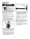
Heating Element
Replacement
Electrical Shock Hazard
Disconnect power before
servicing.
Replace all parts and panels
before operating.
Failure to do so can result
in death or electrical shock.
WARNING
Replacement heating elements must be of the same
style and voltage/wattage rating as the ones originally
in the water heater. This information can be found on
the fl ange or terminal block of the element or on the
water heater data plate.
1. Turn off the electric power to the water heater.
2. Drain the water heater as directed under “Draining
and Flushing” section.
3. Remove the access cover(s), then remove the insula-
tion and element cover(s). Remove the plastic guard
covering electric wiring.
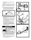
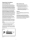
4. Disconnect the electric wires from the heating
element (See Figure 13). Remove the screw-in
element by turning the element counterclockwise
with an SAE 1-
1/
2 inch socket wrench or use an ele-
ment wrench. Remove the existing gasket.
5. Clean the area with a soft cloth to remove any debris
where the gasket fi ts to the tank. If replacing the bot-
tom element, remove the accumulated sediment on
the bottom of the tank. Refer to “Draining and Flush-
ing.”
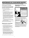
6. Make sure the replacement element has the correct
voltage and wattage rating. Lubricate the new gasket
with a few drops of dishwashing soap, position the
new gasket on the element and insert it into the water
heater tank (See Figure 14). Tighten the element by
turning it clockwise until secure.
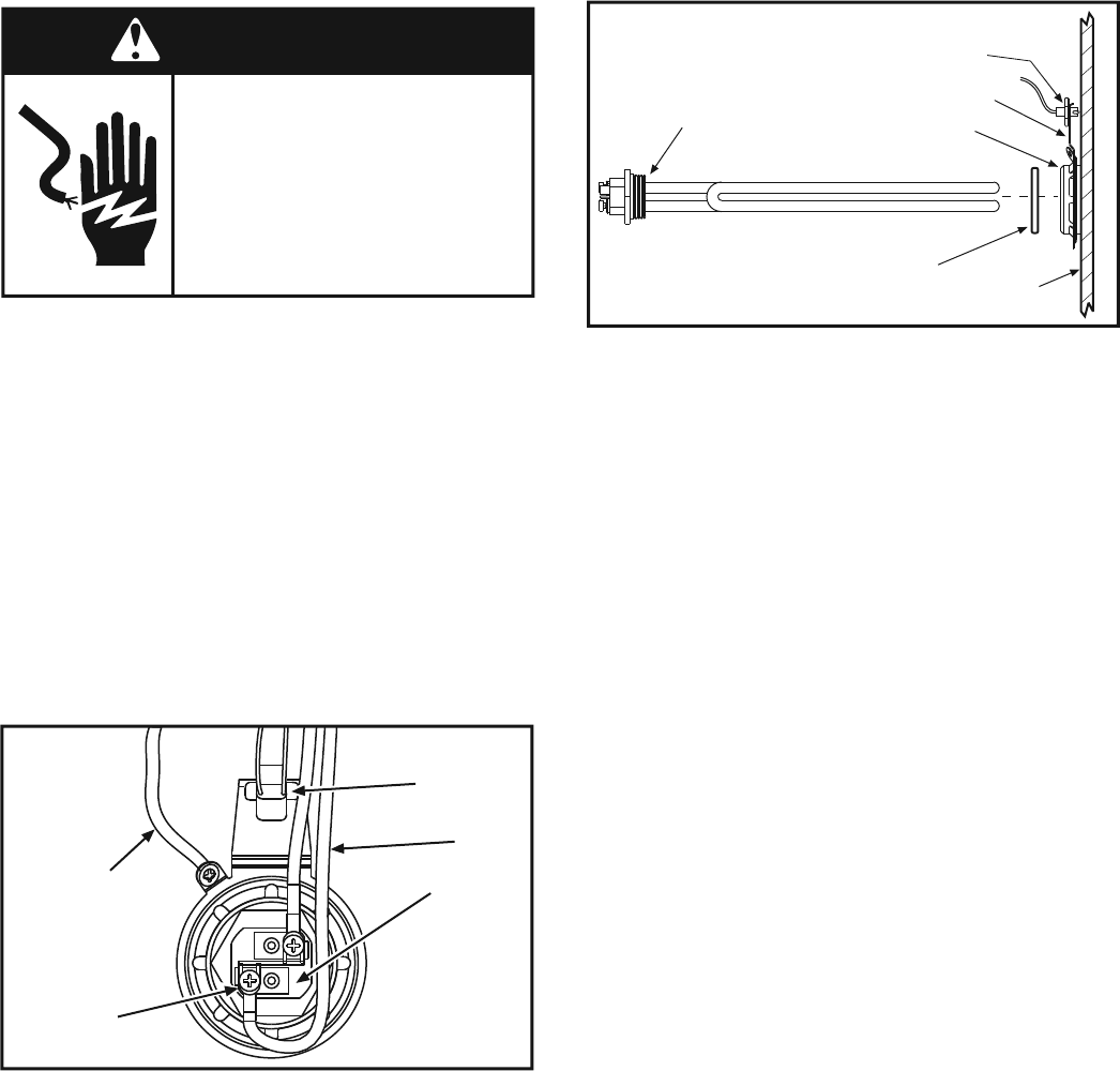
Ground
Wire (green)
Figure 13
Element Wiring
Connection
Screws
Wires
Element
Lower Thermistor
Sensor
7. Close the drain valve. Open the nearest hot water
faucet and allow the tank to fi ll completely with
water. To purge the lines of any excess air and
sediment debris, keep the hot water faucet open for
3 minutes after a constant fl ow of water is obtained.
Close the faucet.
8. Check for leaks around element(s) and other connec-
tions.
9. Connect the electric wires to the heater element.
make sure all wires are secure. Reinstall plastic guard
covering wiring.
10. Replace the insulation and access door(s).
IMPORTANT: Operation of this water heater without
access doors or insulation could result in much higher
temperatures than the desired set point, increasing the
risk of scald injury. Do not operate water heater with the
access doors or insulation removed.
11. Reconnect the electric power to the water heater.
12. Turn the electrical power on to turn the water heater
on. NOTE: the water heater will conduct a system
diagnostic prior to operation.
Figure 14
Element and Thermistor
Sensor
Spud
Screw-in Element
Gasket
Lower Thermistor Sensor
(Must Have Good Contact With Tank,
Check After Replacing Element)
Sensor Bracket
Tank