77Part number 550-141-850/0699
• Installation • Start-Up • Parts • Maintenance
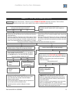
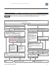
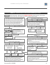
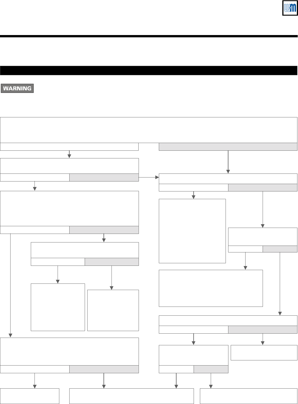
CHART 4
—
PRES SWITCH & POWER
lights flashing
Electrical shock hazard — Wherever you see
▲
TURN OFF POWER
▲
, follow the instructions. Failure to follow
instructions could result in severe personal injury, death or substantial property damage.
Boiler should be in normal operating
sequence.
Observe operation until thermostat is
satisfied and blower has completed its post-
purge cycle.
Drain condensate.
Retest.
• Remove one of the red wires connected to the pressure
switch.
• Check continuity across the switch terminals.
Does the ohmmeter indicate the switch is closed?
Replace control module.
Retest.
Check air pressure switch per manual Section
XI
.
Replace if necessary. Retest.
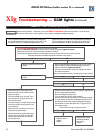
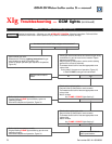
Replace blower
motor. (Also check
blower housing
assembly. Replace if
necessary.)
Retest.
Properly position
blower wheel on
blower motor shaft
and tighten set screw.
(Or replace blower
housing assembly.)
Retest.
No Yes
Wait 45 seconds.
Does blower motor operate?
No Yes
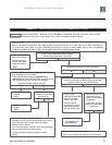
• Remove
BLOWER
plug (
Figure 34, Item 3
) from plug
receptacle of control module.
• Place voltmeter leads across the
120 VAC N
and
120 VAC H
pins of the
BLOWER
receptacle.
Does the voltmeter indicate
120 VAC
?
▲
TURN OFF POWER
▲
at service switch.
Does blower wheel turn freely by hand?
No Yes
No Yes
No Yes
Is blower wheel turning at speed of blower motor?
Check condensate trap. Is there condensate present?
No Yes
Are vent or combustion air
passages blocked?
No Yes
Clear passages and recycle boiler.
Recheck boiler operation.
No Yes
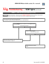
Wait 5 minutes.
Is purge light flashing?
• Reset boiler control by turning off power at service switch or turning down thermostat for at least 45 seconds.
• Thermostat should call for heat and appropriate zone valves open.
Does blower motor operate?
▲
TURN OFF POWER
▲
at
service switch.
• Properly position blower
wheel on blower motor
shaft and tighten set
screw. (Or replace blower
housing assembly.)
• Retest.
No Yes


