


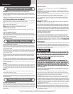

Please Do Not Return This Product To The Store. Contact your local Wayne-Dalton dealer. To find your local Wayne-Dalton dealer,
refer to your local yellow pages business listings or go to the Find a Dealer section online at www.Wayne-Dalton.com
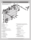
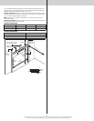
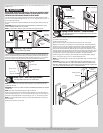
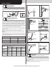
tal track to the flag angle/wall angle with (2) 1/4”-20 x 5/8” carriage bolts and (2) 1/4”-20
flange hex nuts.
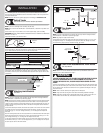
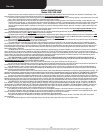
WARNING WARNING
DO NOT RAISE DOOR UNTIL HORIZONTAL TRACKS ARE SECURED AT REAR,
AS OUTLINED IN STEP, REAR BACK HANGS, OR DOOR COULD FALL FROM
OVERHEAD POSITION CAUSING SEVERE OR FATAL INJURY.
Level the horizontal track assembly and bolt the horizontal track angle to the first encoun-
tered slot in the flag angle/wall angle using (1) 3/8”-16 x 3/4” hex head bolt and (1) 3/8”-16
hex nut. Repeat for other side.
Remove the nail that was temporarily holding the top section in place, installed in step, Top
Section.
IMPORTANT: FAILURE TO REMOVE NAIL BEFORE ATTEMPTING TO RAISE DOOR COULD
CAUSE PERMANENT DAMAGE TO TOP SECTION.
NOTE: If an opener will be installed, position horizontal tracks slightly above level.
(2) 1/4”-20 x 5/8”
Carriage bolts
(2) 1/4”-20
Flange hex nuts
Horizontal
track
3/8”-16
Hex nut
Horizontal
track angle
3/8”-16 x 3/4”
Hex head bolt
Horizontal
track
Flag angle
Flag angle
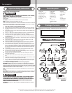
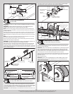
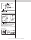
Adjusting Top Fixtures
Tools: 7/16” Wrench, Step ladder
14
With horizontal tracks installed, you can now adjust the top fixtures. Vertically align the top
section of the door with the lower sections. Once aligned, position the top fixture slide, out
against the horizontal track. Maintaining the slide’s position, tighten the (2) 1/4”-20 flange
hex nuts to secure the top fixture slide to the top fixture base. Repeat for other side.
Top fixture slide
(2) 1/4”- 20
Flange hex nuts
Horizontal track
Top section
Top fixture base
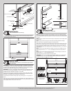
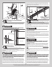
Head Plates / End Bearing Brackets
Tools: Step ladder, Power drill, 7/16” Socket driver
15
NOTE: Refer to illustrations to determine which head plates / end bearing brackets was
supplied with your door.
IMPORTANT: RIGHT AND LEFT HAND IS ALWAYS DETERMINED FROM INSIDE THE BUILDING
LOOKING OUT.
NOTE: Head plates / End bearing brackets are right and left hand.
Attach the left hand head plate / end bearing bracket through on top of the left hand hori-
zontal track angle using (2) 3/8”-16 x 3/4” hex head bolts and (2) 3/8”-16 nuts. Secure the
head plates / end bearing bracket to the jamb using (2) 5/16” x 2” lag screw(s), as shown.
NOTE: It is recommended that the 5/16” lag screws are pilot drilled using a 3/16” drill bit,
prior to fastening.
Repeat the same process for other side.
(2) 3/8”-16
Hex nuts
(2) 3/8”-16 x 3/4”
Hex head bolts
Horizontal
track angle
(2) 5/16” x 2”
Lag screws
Horizontal
track angle
Left hand head
plate / end bracket
Left hand head
plate / end bracket
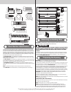
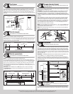
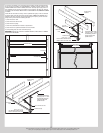
Spring Anchor Bracket / Center Bracket
Tools: Step ladder, Power drill, 7/16” Socket driver, 1/4” Torx bit, Level,
Tape measure, Pencil
16
NOTE: Refer to the Package Contents and or Parts Breakdown to determine if your door
came with a coupler assembly.
Locate the center of the door.
Mark a vertical pencil line on the mounting surface above the door, at the center.
Measure from the center of the bearing, in one of the head plates / end bearing brackets,
downwards, to the top the door. Using that measurement, measure that distance upwards
from the top of the door to the mounting surface and mark a horizontal pencil line which
intersects the vertical pencil line(s). Align the edge of the spring anchor bracket(s) / center
bracket(s) with the vertical pencil line and the center of the spring anchor bracket(s) / center
bracket(s) with the horizontal pencil line; this is to ensure the torsion shaft is level between
the spring anchor bracket / center bracket and head plates / end bearing brackets.
Attach the spring anchor bracket(s) / center bracket(s) to the mounting surface, using (2)
5/16” x 2” lag screws and (1) 5/16” x 2” tamper-resistant lag screw.
NOTE: It is recommended that 5/16” lag screws are pilot drilled using a 3/16” drill bit, prior
to fastening.
IMPORTANT: USE A 5/16” X 1-5/8” TAMPER-RESISTANT LAG SCREW INSTEAD OF THE
5/16” X 2” TAMPER-RESISTANT LAG SCREW IF MOUNTING SURFACE IS MOUNTED OVER
MASONRY. TAMPER-RESISTANT LAG SCREW MUST BE ATTACHED THROUGH THE BOTTOM
SLOT OF THE SPRING ANCHOR BRACKET(S) / CENTER BRACKET(S).
Spring anchor
bracket /
Center bracket
Vertical line
Mounting surface
Horizontal line
Center of
head plate /
end bearing
bracket
Equal distance (top of door section to horizontal line)
9