


INSTALLATION
Before installing your door, be certain that you have read and followed all of the instruc-
tions covered in the pre-installation section of this manual. Failure to do so may result in an
improperly installed door.
NOTE: Reference TDS 160 for general garage door terminology at www.dasma.com.
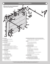
Vertical Tracks
Tools: Power Drill, 5/16” Drill Bit, Hacksaw, Tape Measure
1
NOTE: If you have a wall angle track assembly, skip this step.
NOTE: Refer to Door Section Identification / Parts Breakdown, to determine if you have verti-
cal tracks.
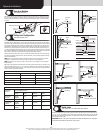
Vertical tracks may or may not have to be cut to the proper length, prior to installing.
IMPORTANT: VERTICAL TRACKS ARE NOT REQUIRED TO BE CUT DOWN IF YOU HAVE DOOR
HEIGHTS 7’-0” OR 8’-0”.
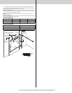
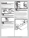
Determine the radius of your horizontal track.
12”
Stamped
radius
Horizontal
track
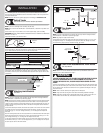
Refer to the vertical track cutting chart to determine the length needed to be cut off at the top
of the vertical tracks. Using this measurement, measure and cut the vertical track off at the
top, as shown. Remove any burrs from the cut edge of vertical track.
Vertical Track Cutting Chart
Horizontal Track Radius Vertical Track Cut Length
10” Or 12” Radius Door Height Minus 10”
14” Radius Door Height Minus 8”
Vertical
track
Top of
track
Measure and cut
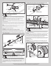
Now, two holes must be drilled into the top of the cut vertical track. Using the illustration
shown below, mark and drill the hole locations using a 5/16” drill bit. Once the holes have
been drilled, remove any burrs from the drilled holes. Repeat the same process for the other
vertical track.
Vertical
track
Measure and drill
5/16” Holes
5/8”
5/8”
1/2”
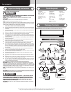
Attaching Jamb Brackets
Tools: None
2
NOTE: If you have a wall angle track assembly, skip this step. Refer to Package Contents /
Parts Breakdown, to determine if you have flag angles.
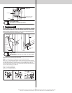
NOTE: The bottom jamb bracket is always the shortest bracket or the lowest number marked
on the jamb bracket. The center jamb bracket is the next tallest or the next higher number
marked on the jamb bracket. If three jamb brackets per side are included with your door, you
will have received a top jamb bracket, which is the tallest or the highest number marked on
the jamb bracket.
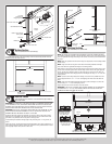
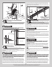
To attach the bottom jamb bracket, locate lower slot pattern of the 1st hole set on the vertical
track. Align the slot in the jamb bracket with the lower slot pattern. Loosely, secure jamb
bracket using (1) 1/4”-20 x 5/8” carriage bolt and (1) 1/4”-20 flange hex nut. Repeat for
other side.
Place the center jamb bracket over the slot pattern that is centered between the bottom jamb
bracket and flag angle of the 2nd hole set. Loosely, secure jamb bracket using (1) 1/4”-20 x
5/8” carriage bolt and (1) 1/4”-20 flange hex nut. Repeat for other side.
If a top jamb bracket was included, loosely secure it to vertical track using the slot pattern in
the 3rd hole set and (1) 1/4”-20 x 5/8” carriage bolt and (1) 1/4”-20 flange hex nut. Repeat
the same process for the other vertical track.
Jamb
bracket
1/4”- 20 x 5/8”
Carriage bolt
1/4”- 20
Flange hex nut
Jamb bracket
in place
Slot pattern
Vertical track
1st hole set
2nd hole set 3rd hole set
Top of track
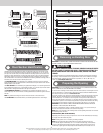
Flag Angles
Tools: None
3
NOTE: If you have a wall angle track assembly, skip this step. Refer to Package Contents /
Parts Breakdown, to determine if you have flag angles.
NOTE: Flag angles are right and left handed.
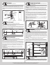
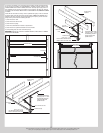
Hand tighten the left hand flag angle to the left hand vertical track using (2) 1/4”-20 x 5/8”
carriage bolts and (2) 1/4”-20 flange hex nuts. Repeat for other side. Flange nuts will be
secured after flag angle spacing is completed in step, Top Section.
(2) 1/4”- 20 x 5/8”
Carriage bolts
Flag angle
Vertical
track
(2) 1/4”-20
Flange hex nuts
Cable Drum Assemblies and Track Rollers
Tools: Tape Measure
4
NOTE: Refer to door section identification, located in the pre-installation section of this
manual or refer to Parts Breakdown on page 2.
WARNING WARNING
FAILURE TO ENSURE TIGHT FIT OF CABLE LOOP OVER MILFORD PIN COULD
RESULT IN COUNTERBALANCE LIFT CABLE COMING OFF THE PIN, AL-
LOWING THE DOOR TO FALL, POSSIBLY RESULTING IN SEVERE OR FATAL
INJURY.
Uncoil the counterbalance lift cables. Starting on the left hand side, place the left hand cable
loop on the left hand milford pin of the bottom corner bracket. Insert a short stem track roller
into the bottom corner brackets and another into the #1 graduated end hinges at the top of
the bottom section.
NOTE: Check to ensure cable loops fits tightly over the milford pins.
NOTE: Larger doors will use long stem track rollers with double graduated end hinges.
NOTE: Verify bottom weather seal is aligned with bottom section. If there is more than 1/2”
excess weather seal on either side, trim weather seal even with bottom section.
Please Do Not Return This Product To The Store. Contact your local Wayne-Dalton dealer. To find your local Wayne-Dalton dealer,
refer to your local yellow pages business listings or go to the Find a Dealer section online at www.Wayne-Dalton.com
6