


Please Do Not Return This Product To The Store. Contact your local Wayne-Dalton dealer. To find your local Wayne-Dalton dealer,
refer to your local yellow pages business listings or go to the Find a Dealer section online at www.Wayne-Dalton.com
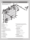
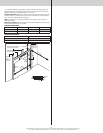
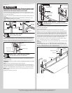
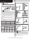
Top Fixtures
Tools: Power drill, 7/16” Socket driver
8
To install the top fixtures, align the top holes in the top fixture base with the second set of
holes in the end cap of the top section. Fasten to section using (4) 1/4”-14 x 5/8” self tap-
ping screws. Secure the top fixture slide to the fixture base loosely using (2) 1/4”-20 x 5/8”
carriage bolts and (2) 1/4”-20 flange hex nuts. The top fixture slide will be tightened and
adjusted later, in step, Adjusting Top Fixture. Insert track roller into top fixture slide. Repeat for
other side.
(4) 1/4”- 14 x 5/8”
Self-tapping screws
Short stem track roller
Top fixture base
Top fixture slide
(2) 1/4”- 20
Flange hex nuts
Top section
2nd Set
End cap
(2) 1/4”- 20 x 5/8”
Carriage bolts
2nd Set
Endcap hole pattern
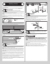
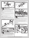
Strut (U-shaped)
Tools: Power drill, 7/16” Socket driver, Tape measure
9
NOTE: If a strut (U-shaped) is supplied, complete this step.
Place the 3” strut over the top rib of the top door section. Fasten each ends of the strut to the
end cap with (2) 1/4”- 20 x 11/16” self drilling screws. Fasten center of the strut as shown
to the rib using (2) 1/4”-14 x 5/8” self tapping screws, one 6” to the left and one 6” to the
right of the center line of the top door section.
Strut
(attached to top rib)
End cap
(2) 1/4”-14 x 5/8”
Self tapping screws
Center line of top section
(2) 1/4”-20 x 11/16”
Self drilling screws
(2) 1/4”-20 x 11/16”
Self drilling screws
6”
6”
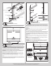
Strut (A-symmetrical)
Tools: Power drill, 7/16” Socket driver, Tape measure
10
NOTE: If an a-symmetrical strut is supplied, complete this step.
Place the a-symmetrical strut over the top rib of the top door section. Fasten each end of
the a-symmetrical strut to the end cap with (2) 1/4”-20 x 11/16” self drilling screws. Fasten
center of the a-symmetrical strut as shown to the rib using (2) 1/4”-14 x 5/8” self tapping
screws, one 6” to the left and one 6” to the right of the center line of the top door section.
Fasten both wall and the long leg of the a-symmetrical strut, as shown using (2) 1/4”-14 x
5/8” self tapping screws every 30-36 inches. (Approximately 18 self tapping screws per 18’
a-symmetrical strut)
IMPORTANT: WHEN SECURING THE A-SYMMETRICAL STRUT TO THE TOP SECTION, IT
IS RECOMMENDED NOT TO INSTALL ANY FASTENERS INTO THE SHORT LEG OF THE A-
SYMMETRICAL STRUT.
(2) 1/4”-14 x 5/8”
Self tapping screws
(2) 1/4”-14 x 5/8”
Self tapping screws
Center line of top section
(2) 1/4”-20 x 11/16”
Self drilling screws
(2) 1/4”-20 x 11/16”
Self drilling screws
30” To 36”
6”
6”
Strut (A-symmetrical)
(attached to top rib)
End cap
Strut (A-symmetrical) side view
Short leg
Long leg
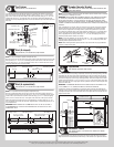
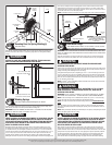
Drawbar Operator Bracket
Tools: Power drill, 7/16” Socket driver, Phillips head screwdriver, Vice
clamps, Tape measure
11
NOTE: If you’re installing a drawbar operator, the drawbar operator bracket must be mounted
and secured prior to installing top section.
IMPORTANT: WHEN CONNECTING A DRAWBAR OPERATOR TYPE GARAGE DOOR OPENER
TO THIS DOOR, A WAYNE-DALTON OPERATOR/ DRAWBAR OPERATOR BRACKET MUST
BE SECURELY ATTACHED TO THE TOP SECTION OF THE DOOR, ALONG WITH ANY STRUT
PROVIDED WITH THE DOOR. THE INSTALLATION OF THE DRAWBAR OPERATOR MUST BE AC-
CORDING TO MANUFACTURER’S INSTRUCTIONS AND FORCE SETTINGS MUST BE ADJUSTED
PROPERLY.
Prior to installing the top section, locate the center of the top section and seat the drawbar
operator bracket on top of the top section. For retro fit applications, the drawbar operator
bracket must be aligned with an existing drawbar operator and positioned on top section
so it bridges the transition point of the section thickness. Install (2) #12 x 1/2” phillips head
screws on the back side of drawbar operator bracket. Clamp drawbar operator bracket to
strut (if supplied) with vice clamps. Attach (5) 1/4” - 14 x 5/8” self-tapping screws to the
drawbar operator bracket. Remove vice clamps.
NOTE: If a strut was installed, you can use two of the 1/4” - 20 x 11/16” self-drilling screws
previously used to attach the strut instead of two 1/4”-14 x 5/8” self-tapping screws when
attaching drawbar operator bracket to strut.
NOTE: When attaching drawbar operator bracket to top section with strut, apply additional
pressure to thread into the strut.
(2) #12 x 1/2”
Phillips head screws
1/4”- 14 x 5/8”
Self-tapping screws
Drawbar operator
bracket
Backside of
drawbar operator
bracket
Top Section
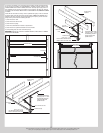
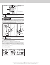
Tools: Hammer, Step ladder, Tape measure
12
Place the top section in the opening. Temporarily secure the top section by driving a nail into
the header near the center of the door and bending it over the top section. Now, flip up the
graduated end and center hinge leaves, hold tight against section, and fasten center hinges
first and end hinges last (refer to step, Stacking Sections). Vertical track alignment is critical.
Position flag angle between 1-11/16” (43 mm) to 1-3/4” (44 mm) from the edge of the door;
tighten the bottom lag screw. Flag angles must be parallel to the door sections. Repeat same
process for other side.
IMPORTANT: THE DIMENSION BETWEEN THE FLAG ANGLES MUST BE DOOR WIDTH PLUS
3-3/8” (86MM) TO 3-1/2” (89 MM) FOR SMOOTH, SAFE DOOR OPERATION.
Complete the vertical track installation by securing the jamb bracket(s) and tightening the
other lag screws. Push the vertical track against the track rollers so that the track rollers are
touching the deepest part of the curved side of the track; tighten all the track bolts and nuts.
Repeat for other side.
Top section
Top
section
Nail
Door width
+ 3-3/8” to 3-1/2”
1-11/16”
to 1-3/4”
Flag
angle
Flag angle
Vertical track
against track rollers
Horizontal Tracks
Tools: Ratchet wrench, 7/16” Socket, 9/16” Socket, 9/16” Wrench,
level, Step ladder
13
To install horizontal track, place the curved end over the top track roller of the top section.
Align the bottom of the horizontal track with the top of the vertical track. Tighten the horizon-
8