


Please Do Not Return This Product To The Store. Contact your local Wayne-Dalton dealer. To find your local Wayne-Dalton dealer,
refer to your local yellow pages business listings or go to the Find a Dealer section online at www.Wayne-Dalton.com
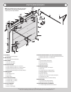
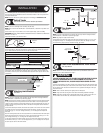
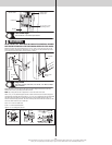
Spring anchor bracket
/ Center bracket
(1) 5/16” X 1-5/8” or (1)
5/16” x 2” Tamper-
resistant lag screw
(2) 5/16” x 2”
Lag screws
Vertical
line
Mounting
surface
Horizontal
line
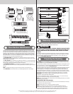
Torsion Spring Assembly
Tools: Step Ladder
17
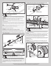
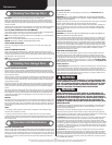
IMPORTANT: RIGHT AND LEFT HAND IS ALWAYS DETERMINED FROM INSIDE THE BUILDING
LOOKING OUT.
IMPORTANT: ON SINGLE SPRING APPLICATIONS, ONLY A LEFT HAND WOUND (BLACK
WINDING CONE), WHICH GOES ON THE RIGHT HAND SIDE IS REQUIRED.
NOTE: Identify the torsion springs provided as either right hand wound (red winding cone),
which goes on the LEFT HAND SIDE or left hand wound (black winding cone), which goes on
the RIGHT HAND SIDE.
Facing the inside of the door, lay the torsion shaft on the floor. Lay the torsion spring with the
black winding cone and the black cable drum at the right end of the torsion shaft. Lay the
torsion spring with the red winding cone and the red cable drum at the left end of the torsion
shaft.
NOTE: The set screws used on all torsion winding cones and cable drums are now colored
red. DO NOT identify right and left hand by the set screw color.
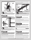
Slide the spring anchor bracket bushing / center bracket bushing onto the torsion shaft fol-
lowed by the torsion springs and cable drums.
IMPORTANT: THE SPRING ANCHOR BRACKET BUSHING / CENTER BRACKET BUSHING, TOR-
SION SPRINGS, AND CABLE DRUMS MUST BE POSITIONED, AS SHOWN.
With assistance, pick up the torsion spring assembly and slide one end of the torsion shaft
through the head plate / end bearing bracket. Lay the middle of the torsion shaft into the
center bracket. Slide the other end of the torsion shaft into the other head plate / end bearing
bracket. Position the torsion shaft so that equal amounts of the shaft extend from each head
plates / end bearing brackets.
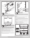
Torsion shaft
Spring anchor bushing /
center bracket bushing
Right hand wound,
red winding cone
(left hand side)
Left hand wound,
black winding cone
(right hand side)
Right hand cable
drum, black
Left hand cable
drum, red
Left hand head plate
/ end bearing
bracket
Equal spacing
Right hand head plate
/ end bearing bracket
Torsion shaft
Spring anchor bushing /
center bracket bushing
Spring anchor bracket /
center bracket
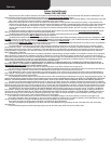
Torsion Spring Attachment
Tools: Step Ladder, Ratchet Wrench, 9/16” Socket, 9/16” Wrench
18
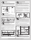
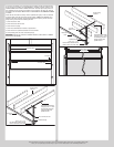
Slide the spring anchor bushing / center bracket bushing into the spring anchor bracket /
center bracket. Align the stationary spring cone(s) with the holes in the spring anchor bushing
/ center bracket bushing. Secure the torsion spring(s) to the spring anchor assembly / center
bracket assembly with (2) 3/8”-16 x 1-1/2” hex head bolts and (2) 3/8”-16 nuts.
IMPORTANT: THE SPRING WARNING TAG SUPPLIED MUST BE SECURELY ATTACHED TO THE
STATIONARY SPRING CONE IN PLAIN VIEW. SHOULD A REPLACEMENT SPRING WARNING
TAG BE REQUIRED, CONTACT WAYNE-DALTON FOR FREE REPLACEMENTS.
Spring anchor bushing /
center bracket bushing
Stationary
spring cone
Spring anchor bracket
/ center bracket
Torsion
spring
Stationary
spring cone
Torsion spring
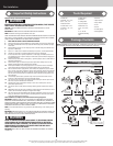
HIGH SPRING TENSION CAN CAUSE
SERIOUS INJURY OR DEATH.
DO NOT adjust, repair or remove springs or parts to
which springs are connected, such as steel brack-
ets, cables, wood blocks, fasteners or other parts of
the counterbalance system.
Adjustments or repairs must ONLY be made by a
trained door systems technician using proper tools
and instructions.
DO NOT remove, cover or paint over this tag. Prod-
uct user should inspect this tag periodically for
legibility and should order a replacement tag from
the door manufacturer, as needed.
©Copyright 2010 Overhead Door Corporation
102081 REV2 06/24/2010
Spring anchor assembly / center bracket assembly
Stationary spring cone(s)
(1) 3/8”-16 x 1-1/2”
Hex head bolt
(1)
3/8”-16
Nut
Torsion
spring
Torsion
spring
(1) 3/8”-16
Nut
(1) 3/8”-16 x 1-1/2”
Hex head bolt
Spring warning tag
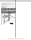
Counterbalance Lift Cables
Tools: Step Ladder, Locking Pliers, 3/8” Wrench
19
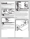
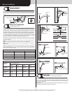
Starting on the left hand side, thread the counterbalance lift cable up and around the front
side of the left hand cable drum.
IMPORTANT: VERIFY THAT THERE ARE NO COUNTERBALANCE LIFT CABLE OBSTRUCTIONS.
Hook the counterbalance lift cable into the left hand cable drum. Slide the left hand cable
drum up against the left hand head plate / end bearing bracket. Counterbalance lift cable
should terminate at the 3 o’clock position. Tighten the (2) set screws in the drum to 14-15 ft.
lbs. of torque (once set screws contact the shaft, tighten screws one full turn).
Rotate the left hand drum and torsion shaft until counterbalance lift cable is taut. Now attach
locking pliers to the torsion shaft and brace locking pliers up against jamb to keep counter-
balance lift cable taut.
Repeat for right hand side.
IMPORTANT: INSPECT EACH COUNTERBALANCE LIFT CABLES MAKING SURE THEY ARE
SEATED PROPERLY ONTO THE CABLE DRUMS AND THAT BOTH COUNTERBALANCE LIFT
CABLES HAVE EQUAL TENSION.
Left cable drum
Counterbalance lift
cable hooked in
cable drum
Counterbalance
lift cable
Left hand head
plate / end
bearing bracket
10