


7
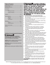
Please Do Not Return This Product To The Store. Contact your local Wayne-Dalton dealer. To find your local Wayne-Dalton dealer, refer to your
local yellow pages/business listings or go to the Find a Dealer section online at www.wayne-dalton.com
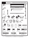
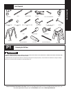
Tools Needed:
INSTALLATION
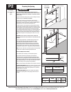
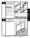
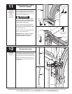
Begin the installation of the door by checking the opening. It must be the same size as the door. Vertical jambs must be plumb and level with header. Side clearance, from
edge of door to wall, must be a minimum of 3-1/2” (89mm) on each side.
IMPORTANT: STAINLESS STEEL OR PT 2000 COATED LAG SCREWS MUST BE USED WHEN INSTALLING CENTER BEARING BRACKETS, END BRACKETS, JAMB BRACKETS,
OPERATOR MOUNTING/SUPPORT BRACKETS AND DISCONNECT BRACKETS ON TREATED LUMBER (PRESERVATIVE-TREATED). STAINLESS STEEL OR PT 2000 COATED LAG
SCREWS ARE NOT NECESSARY WHEN INSTALLING PRODUCTS ON UN-TREATED LUMBER.
IMPORTANT: WHEN INSTALLING 5/16” DIAMETER LAG SCREWS USING AN ELECTRIC DRILL/DRIVER, THE DRILL/DRIVER’S CLUTCH MUST BE SET TO DELIVER NO MORE THAN
200 IN. LBS. OF TORQUE. FASTENER FAILURE COULD OCCUR AT A HIGHER SETTING.
NOTE: It is recommended that 5/16” lag screws be pilot drilled using a 3/16” drill bit, prior to fastening.
Installation
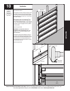
Lift handle placement reference on single wide doors
20” Min. To
30” max.
Lift handle placement reference on double wide doors
20” Min. To 30” max.
1
Tape Measure
Pencil
Power Drill
1/16” Drill Bit
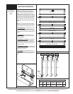
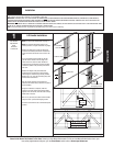
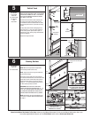
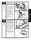
Lift Handle Installation
NOTE: For door section identification see page 4.
NOTE: Use reference illustrations below for lift
handles positions on singles and double car garage.
Measure the width of the center stile which will
receive the lift handle(s). Divide that measurement
in half and mark a vertical line on the center of the
stile.
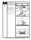
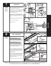
If you are installing two lift handles on the stile,
you will need to measure from the edge of the
center stile to the center line mark. Divide that
measurement in half and draw a second and third
vertical line parallel to the previously made center
line mark.
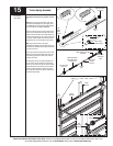
Measure the height of the panel. Divide that
measurement in half and mark a horizontal line,
intersecting the vertical line(s) previously marked.
Measure up 3 7/8” from the intersecting line(s) and
mark another horizontal line.
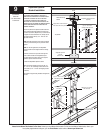
Use the point(s) where the top horizontal line
intersects the vertical line(s) to locate the top hole of
the lift handle(s).
Using the lift handle as a template, mark this
location on the stile. Keeping the carriage handle
aligned on the vertical line, mark the lower carriage
handle hole on the stile.
Drill a 1/16” pilot hole, then fasten both lift handles
using #10 X 5/8” pan head self tapping screws.
If the door came with two sets of lift handles repeat
process.
Lock section
center stile
Locate the center
Locate the
centers
Lift
handles
Horizontal line
#10 X 5/8” pan head
self tapping screws
SINGLE WIDE DOORS
DOUBLE WIDE DOORS
3-7/8”