


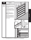

10
Please Do Not Return This Product To The Store. Contact your local Wayne-Dalton dealer. To find your local Wayne-Dalton dealer, refer to your
local yellow pages/business listings or go to the Find a Dealer section online at www.wayne-dalton.com
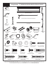
Tools Needed:
Tools Needed:
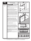
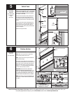
Bottom
section
5/16 X 1-5/8”
Lag screws
Flagangle
Vertical track
assembly
Jamb
Bracket
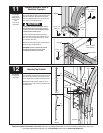
5
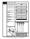
Vertical Track
3/16” Drill Bit
Power Drill
7/16” Socket Driver
Tape Measure
Level
Step Ladder
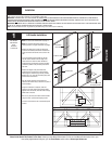
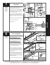
IMPORTANT: THE TOPS OF THE VERTICAL TRACKS
MUST BE LEVEL FROM SIDE TO SIDE. IF THE BOTTOM
SECTION WAS SHIMMED TO LEVEL IT. THE VERTICAL
TRACK ON THE SHIMMED SIDE, MUST BE RAISED
THE HEIGHT OF THE SHIM.
Position the left hand vertical track assembly over
the rollers of the bottom section. Make sure the
counterbalance cable is located between the rollers
and the door jamb. Drill 3/16” pilot holes for the lag
screws.
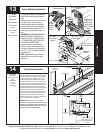
Loosely fasten jamb brackets and flagangle to the
jamb using 5/16” x 1-5/8” lag screws. Tighten lag
screw securing bottom jamb bracket to jamb, to
maintain 3/8” to 5/8” spacing. Hang counterbalance
cable over flagangle.
Repeat for the right hand side.
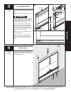
Bottom section
Vertical
track
Roller
3/8” To 5/8”
FLAGANGLE
5/16” x 1-5/8”
Lag screw
Jamb bracket
Lag
screw
Locations
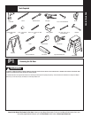
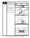
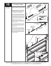
Stacking Sections
NOTE: For door section identification see page 4.
NOTE: Make sure hinges leafs are flipped down,
when stacking another section on top.
NOTE: Larger doors will use long shaft rollers with
double wide end hinges.
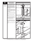
Place rollers in hinge tubes of the second section
(lock section). With assistance, lift second section and
guide rollers into the vertical tracks. Keep sections
aligned and fasten hinges to connect the sections
using 1/4” - 14 x 5/8” self-tapping screws. Repeat
for other section(s) except top section.
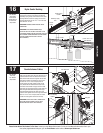
IMPORTANT: PUSH & HOLD THE HINGE LEAFS
AGAINST SECTION WHILE SECURING WITH 1/4” - 14
X 5/8” SELF-TAPPING SCREWS. END HINGES HAVE
(2) SCREWS AND INTERMEDIATE HINGES HAVE (3)
SCREWS. DOUBLE END HINGES HAVE (5) SCREWS.
NOTE: Install lock at this time (sold separately) see
instructions in OPTIONAL SIDELOCK INSTALLATION
on page 21.
6
Power Drill
7/16” Socket Driver
INTERMEDIATE HINGES
(3) 1/4” - 14 X 5/8”
Self-tapping screws
Lock
section
SINGLE END HINGES
(LEFT HAND SHOWN, RIGHT HINGE
SYMMETRICALLY OPPOSITE)
Bottom
section
Hinge leafs must be flipped
down
(2) 1/4” - 14 X 5/8”
Self-tapping screws
DOUBLE END HINGES
(LEFT HAND SHOWN, RIGHT HINGE
SYMMETRICALLY OPPOSITE)
(5) 1/4” - 14 X 5/8”
Self-tapping screws