


11
Please Do Not Return This Product To The Store. Contact your local Wayne-Dalton dealer. To find your local Wayne-Dalton dealer, refer to your
local yellow pages/business listings or go to the Find a Dealer section online at www.wayne-dalton.com
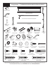
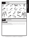
Tools Needed:
Tools Needed:
INSTALLATION
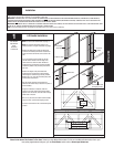
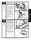
Top Brackets
Power Drill
7/16” Socket
Driver
Phillips Head
Screwdriver
(4) 1/4” - 14 X 5/8”
Self tapping screws
Top
bracket
base
1st
Set
2nd
Set
Top section
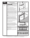
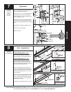
7
To install the L-shaped top brackets, align the top
holes in the top bracket base with the second set of
holes in the endcap of the top section.
Fasten using (4) 1/4” - 14 x 5/8” self tapping screws.
Secure the top bracket slide to the bracket base
loosely using (2) 1/4” - 20 x 5/8” carriage bolts and
(2) 1/4” - 20 flanged hex nuts.
Fasten (2) #8 x 1-21/32” Quadrex Pan Head screws,
one in the middle hole of the top bracket base, the
other in the corresponding hole below the top bracket
base.
The bracket will be tightened and adjusted in Step
12.
Insert rollers into top bracket slide.
Repeat for other side.
Top
bracket
base
Top bracket
slide
(2) 1/4”- 20
Flange hex nuts
Top section
(2) 1/4”- 20 X 5/8”
Carriage bolts
Roller
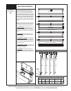
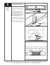
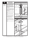
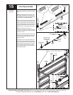
NOTE: For door section identification see page 4.
IF YOU HAVE DOOR WIDTHS 8’0” - 10’0”:
Doors will be supplied with (1) 3” asymmetrical u-bar
for the top sections. Make sure the placement is
correct by checking it with the illustrations shown.
IF YOU HAVE DOOR WIDTHS 12’0” - 18’0”:
Doors will be supplied with (3) 3” asymmetrical
u-bars for the top, intermediate II, lock, and bottom
sections. Placement of the u-bar is different for
each section. Make sure the placement is correct by
checking it with the illustrations shown.
Place the 3” asymmetrical u-bar over the top rib
of the top, intermediate II and lock section and the
bottom rib of the bottom section. Fasten each end of
the u-bar to the endstile with (2) 1/4”- 20 x 11/16”
self drilling screws.
Fasten center of the u-bar as shown to the rib using
(2) 1/4”- 14 x 5/8” self tapping screws 6” off of the
center of the door section. Fasten both walls of the
u-bar as shown using 1/4”- 14 x 5/8” self tapping
screws every 30 - 36 inches.
Approximately 18 self tapping screws per 18’ u-bar.
U-Bar - Asymmetrical
Power Drill
7/16” Socket Driver
8
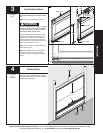
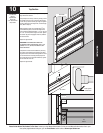
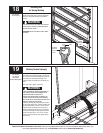
BOTTOM RIB OF BOTTOM SECTION
TOP RIB OF LOCK SECTION
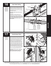
TOP RIB OF TOP SECTION
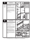
(2) 1/4”-20 X 5/8”
Self tapping screws
Lock section: U-bar placement is on the
top rib in a reverse fashion
(2) 1/4”-20 X 11/16”
Self drilling screws
30” To 36”
(2) 1/4”-20 X 5/8”
Self-tapping screws
(2) 1/4”-20 X 11/16”
Self-drilling screws
(2) #8 x 1-21/32”
Quadrex pan
head screws
Top section: U-bar placement is on
the top rib.
(2) 1/4”-20 X 11/16”
Self-drilling screws
(2) 1/4”-20 X 5/8”
Self-tapping screws
30” To 36”
30” To 36”
Bottom section: U-bar place-
ment on is on the bottom rib