


20
Please Do Not Return This Product To The Store. Contact your local Wayne-Dalton dealer. To find your local Wayne-Dalton dealer, refer to your
local yellow pages/business listings or go to the Find a Dealer section online at www.wayne-dalton.com
Tools Needed:
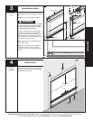
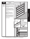
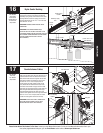
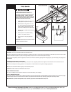
Rear Support Continued...
IMPORTANT: DO NOT SUPPORT THE WEIGHT OF THE
DOOR ON ANY PART OF THE HORIZONTAL TRACK
HANGER THAT CANTILEVERS 4” OR MORE BEYOND A
SOUND FRAMING MEMBER.
NOTE: If rear supports are to be installed over
drywall, use 5/16” x 2” hex head lag screws, and
make sure lag screws engaged solid structural
lumber.
NOTE: 26” Angle must be attached to sound framing
members and nails should not be used.
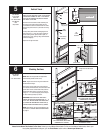
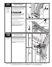
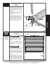
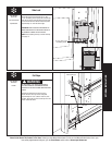
Adjust weather seal (if necessary) to both door jambs
and header. (Temporarily attached in PREPARING The
OPENING on page 6). Avoid pushing weather seal
stop too tightly against face of door.
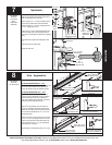
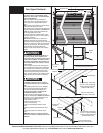
Now, lift door and check its balance. Adjust, if door
lifts by itself (hard to pull down) or if door is difficult
to lift (easy to pull down).
NOTE: Windows will cause the top section to be
significantly heavier than the remaining sections.
Wayne-Dalton attempts to balance the door at the top
and bottom. To prevent any sudden door acceleration
between the top and bottom, we recommend motor
operating all doors with windows. Doors with
windows in the top section should not be manually
operated.
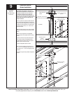
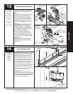
PRIOR TO WINDING OR MAKING ADJUSTMENTS TO
THE SPRINGS, ENSURE YOU’RE WINDING IN THE
PROPER DIRECTION AS STATED IN THE INSTALLATION
INSTRUCTIONS. OTHERWISE, THE SPRING FITTINGS
MAY RELEASE FROM SPRING IF NOT WOUND IN THE
PROPER DIRECTION AND COULD RESULT IN SEVERE
OR FATAL INJURY.
To adjust spring tension, fully close door. Apply vice
grips to track above third roller. Insert a winding bar
into the winding cone. On single spring doors, cable
tension must be maintained by placing vice grips
on torsion tube before loosening set screws in the
winding cone. Push upward on the winding bar while
carefully loosening the set screws in the winding
cone.
BE PREPARED TO SUPPORT THE FULL FORCE OF
THE TORSION SPRING ONCE THE SET SCREWS ARE
LOOSE.
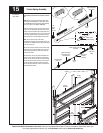
Carefully adjust spring tension 1/4 turn. Retighten
both set screws in the winding cone and repeat
for the other side. Recheck door balance. DO
NOT ADJUST MORE THAN 1/2 TURN FROM THE
RECOMMENDED NUMBER OF TURNS.
If the door still does not operate easily, lower the
door into the closed position, UNWIND THE SPRING(S)
FULLY (Refer to “P1” on page 5 “Removing an old
door and recheck the following the items:
1.) Check the door for level.
2.) Check the torsion tube for level.
3.) Check the track spacing.
4.) Check the counterbalance cables for equal
tension.
5.) Check the track for potential obstruction of the
rollers.
6.) Clamp locking pliers onto track and rewind
springs.
IMPORTANT: IF DOOR STILL DOES NOT OPERATE
PROPERLY, THEN CONTACT A TRAINED DOOR SYSTEM
TECHNICIAN.
3/4” To 7/8”
Perforated angle
(3) 5/16” Bolts
& nuts
Jamb
Weather
seal
Permanently attached weather seal
Horizontal track
Door edges
3/4” To
7/8”
WARNING
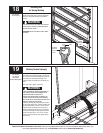
Perforated angle
Perforated angle - bolted using
(2) 5/16” x 1-5/8” hex head lag
screws to ceiling member and
parallel to width of door
Sound framing
members
Horizontal track
Bolt must extend into the
track to serve as a roller stop
Sound framing
members
Bolt must extend into the
track to serve as a roller stop
Horizontal track
Perforated
Angle
Perforated angle -bolted using
(2) 5/16” x 1-5/8” hex head lag
screws to ceiling member and
parallel to width of door
WARNING