


SECTION TSM 685.2 ISSUE C PAGE 8 OF 16
Buttonhead
Screws
Locknut
Inner Magnet
Set Collar
Canister
Bushing
Canister
O-ring
Button Head
Screws
Canister and Casing
Drain Holes
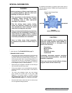
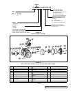
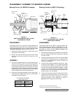
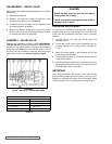
DISASSEMBLY OF COUPLING
FIGURE 9
PUMP, INNER MAGNET AND CANISTER ASSEMBLY
Series MD2-B and MD2-C, All Sizes
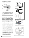
1. Remove the piping to the ports and remove the
capscrews securing the pump to the bracket. Support
the pump with an overhead hoist if possible. Use the
M10 x 120 capscrew (jackscrew) in the bracket to
separate the inner magnet from the outer. (See Figure
Sequence 10).
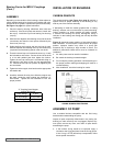
CAUTION !
Use extreme caution, when pulling the in-
ner magnet away from the outer magnet (see
Figure 10). Do not place your fingers between
the pump mounting flange and the face of the
bracket. If you do not completely pull the pump
out it will snap back and could pinch a finger or
hand. Once the inner magnet is removed from
the bracket be careful setting it down as it will
attract any iron or steel object.
2. The canister will contain some liquid, therefore use care
while removing from the pump and pull it straight off.
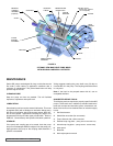
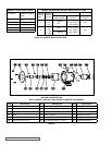
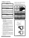
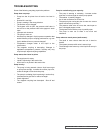
FIGURE 12
MOTOR (OR BEARING CARRIER) AND BRACKET
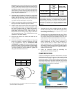
FIGURE 11
INNER MAGNET AND LOCKNUT ASSEMBLY
Motor or
Bearing
Carrier
Bracket
Capscrews
3. Remove the two 6mm buttonhead machine screws and
the set collar. Insert a brass bar through a port between
two rotor teeth and remove the locknut (See Figure 11).
Slide the inner magnet off the shaft. Do not forget this
is a very strong magnet. If further pump disassembly is
required, refer to Step 7 of PUMP DISASSEMBLY.
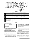
FIGURE 10
PUMP AND BRACKET SEPARATION SEQUENCE
M10x120 CAPSCREW
DO NOT PLACE
FINGERS HERE
M10X120 CAPSCREW
DO NOT PLACE
FINGERS HER
E
(4) 12mm Screw
4. Do not remove the O-ring unless it is bad, especially
if PTFE (derivative) encapsulated. If a new O-ring is
required, follow instructions in the ASSEMBLY section
on page 10.
5. You should be able to visually inspect the outer magnets
from the end of the bracket. If removal is necessary,
start by removing the (4) capscrews (See Figure 12)
and separate the bracket from the motor or bearing
carrier. Loosen the 2 setscrews on the outer shell hub
and slide the outer magnet assembly off the shaft. If
the unit features a bearing carrier, refer to Page 9 for
disassembly of the bearing carrier housing.