


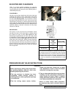
SECTION TSM 685.2 ISSUE C PAGE 12 OF 16
Series MD2-B and MD2-C, All Sizes
DANGER !
Follow these directions exactly to avoid injury
to self or damage to the pumping unit. Be care-
ful to keep the inner and outer magnets at least
(1) foot apart until step 4. Do not engage the
magnets in any other fashion.
1. Inspect the magnets for any steel objects, which may be
attached. Remove any foreign material.
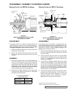
MD2-B Couplings:
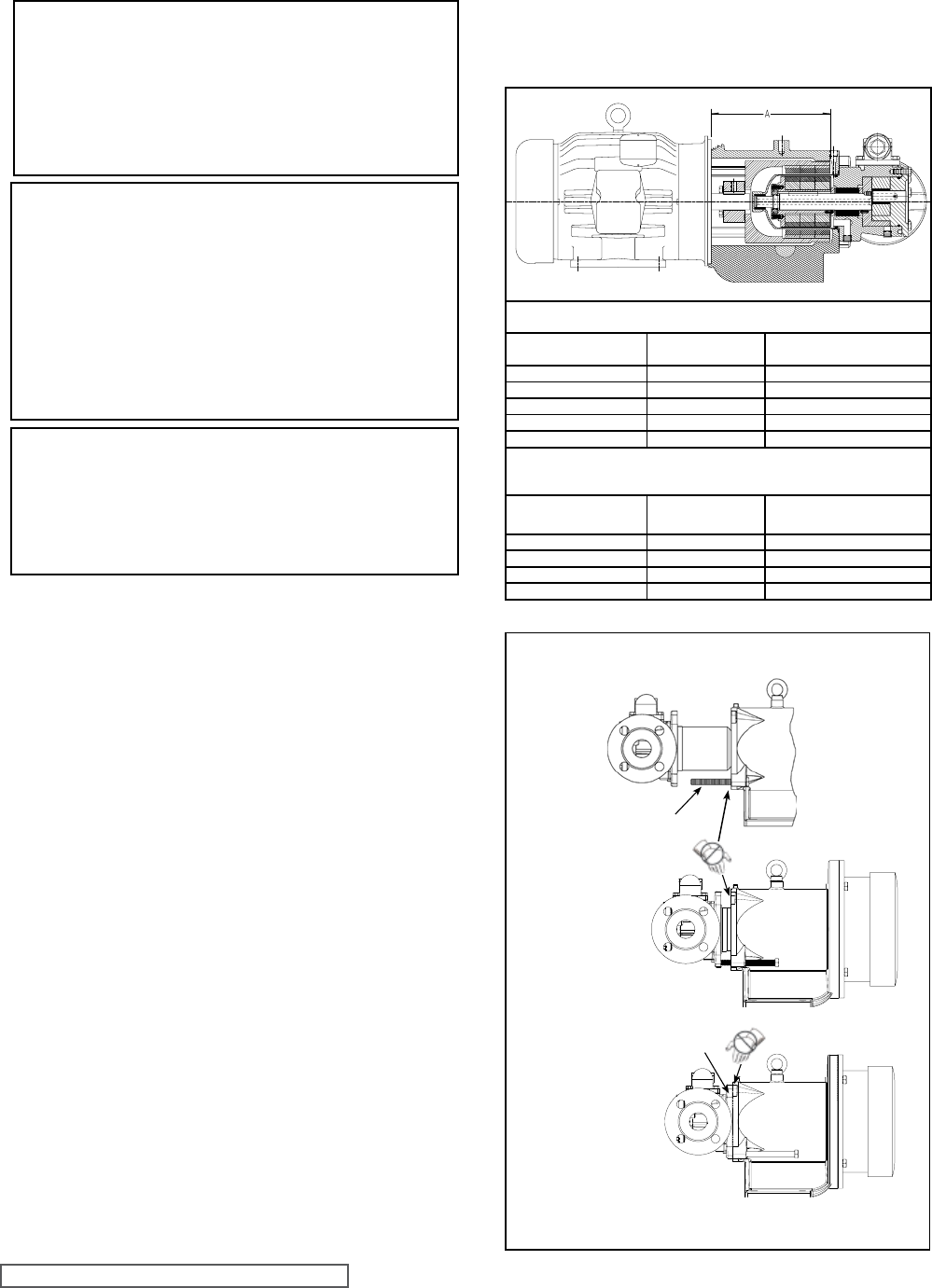
Mount the outer magnet assembly. Locate the outer
magnet assembly per dimension (See Figure 18).
MD2- C Couplings:
Units using a NEMA C-face frame motor will require
an adaptor plate. Mount the adaptor plate to the
motor if it was removed. Mount the outer magnet
assembly. Locate the outer magnet assembly per
dimension (See Figure 18).
Apply Loctite® and tighten the setscrews onto the motor
or bearing carrier key and shaft.
2. If the bracket is not fastened to a base, clamp it down.
Mount the motor or bearing carrier to the bracket. Reach
in and rotate the magnets by hand to make sure there is
no interference. If rubbing occurs check the dimension
in Figure18 or contact the factory.
3. Check to make sure the pump rotates freely by turning
the inner magnet assembly. Inspect the magnet to make
sure it has not picked up any foreign particles, which
could damage the pump. Make sure the canister O-ring
is in good condition and in place. Place the canister onto
the pump and press on until the canister is in contact
with the pump mounting flange.
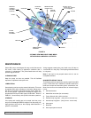
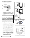
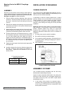
4. Use a fully threaded M10X120mm capscrew (jackscrew)
to guide the canister into the bracket. Thread the
capscrew all the way into the bracket as shown in
Figure Sequence 19.
Use an overhead hoist to support
the pump if possible while guiding the canister into the
bracket opening.
CAUTION !
Do not place fingers onto the front of pump
mounting flange. Align the canister into bore
of the bracket and gently slide it in. When the
magnets start to engage, the unit will finish
engagement on its own very rapidly unless the
M10x120mm capscrew is properly used. Make
sure fingers are not on the front of the pump.
See Figure Sequence 19.
Carefully back out the capscrew while guiding the
canister into the bracket. Secure the pump to the
bracket with four 12mm capscrews.
5. Be certain that the power supply to the pump is “Locked-
out”. Check that pump rotates freely by spinning the
motor fan blades or the bearing carrier shaft.
DANGER!
Be certain that the driving means (motor,
turbine, engine, etc.) has been “locked out”
or made non-operational so that it cannot be
started while work is being done on pump.
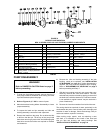
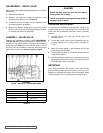
FIGURE 19
PUMP AND BRACKET ASSEMBLY SEQUENCE
DO NOT PLACE
FINGERS HER
E
4) 12mm Capscrew
DO NOT PLACE
FINGERS HERE
M10X120 CAPSCREW
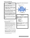
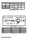
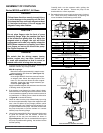
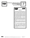
MD2-B Magnets
(Measured from the motor face)
Motor
“A” Dimension
(Inch)
“A” Dimension (Metric)
I.E.C. 110/112 7.73 196.4 MM
I.E.C. 132 8.53 216.5 MM
182TC/184TC 8.11 206 MM
213TC/215TC 8.49 215.7 MM
254TC/256TC 9.11 231 MM
MD2-C Magnets
(I.E.C. Measured from motor face
NEMA Measured from edge of adaptor plate)
Motor
“A” Dimension
(Inch)
“A” Dimension (Metric)
I.E.C.132 10.43 265 MM
I.E.C.160/180 11.61 295 MM
213TC-256TC 10.43 265 MM
284/286TC 10.43 265 MM
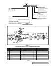
ASSEMBLY OF COUPLING
FIGURE 18
Dimensions are not the same between designs