


SECTION TSM 685.2 ISSUE C PAGE 10 OF 16
INSTALLATION OF BUSHINGS
CARBON GRAPHITE
The canister bushing (see Figure 9 on page 8) requires a
special fixture for proper assembly so the bushing is only
sold as part of the canister assembly.
If attempting to install the carbon graphite idler or casing
bushing, extreme care must be taken to prevent breaking.
Carbon graphite is a brittle material and easily cracked.
If cracked, the bushing will quickly disintegrate. Using a
lubricant on the bushing and mating part will help facilitate
installation.
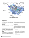
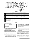
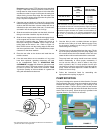
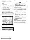
Figure 15
shows the proper position of the casing bushing
after installation. This will require a special fixture for proper
position. Improper location may result in a pump with
excessive slip or requiring a large number of shims. The
additional precautions listed below must be followed for
installation:
1. An arbor press must be used for installation.
2. Be certain the bushing is started straight.
3. Do not stop the pressing operation until the bushing is in
the proper position; starting and stopping will result in a
cracked bushing.
4. After installation, check the bushing for cracks.
FIGURE 15
CASING BUSHING POSITIONING
ASSEMBLY OF PUMP
Use a suitable lubricant compatible with the fluid being
handled when reassembling the pump.
Inspect all parts, especially drilled holes in the casing (for
draining) to make sure they are not plugged. Replace any
worn parts, remove any burrs, and clean all parts before
assembling the pump.
1. If the canister O-ring needs to be replaced, apply a
lubricant to the O-ring and place it into the O-ring groove.
If the O-ring is PTFE (derivative) encapsulated, follow
these special instructions.
ASSEMBLY
Depending on the condition of the bearings, either replace or
repack existing bearings by cleaning and packing with multi-
purpose NLGI # 2 grease. Replace the lip seals if necessary.
See Figure 14, page 9
for lipseal orientation.
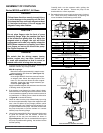
1. Place the bearing housing milled-face down with cast
surface up. If the inner lip seal was removed, install with
the cup up. Install the cup of inner bearing into housing
(cup up).
2. Slide the inner tapered roller bearing cone onto the shaft
(cone down) and then the inner spacer followed by the
outer cone (cone up).
3. Guide shaft into the housing and into the inner lip seal.
Slide the tapered roller bearing outer cup into the housing
(cup down) and the bearing spacer collar onto shaft.
4. Thread in the end cap until it meets the outer cup. Install
the lockwasher and locknut. Secure the end of the shaft
in a vice with padded jaws then tighten the locknut.
Tighten the end cap until there is considerable drag on
the bearings, then back off the end cap approximately
10°. Secure the end cap into position by tightening the
two set screws.
5. Tighten the locknut again, then bend over the appropriate
lockwasher tab.
6. Install the inboard drive key, then slide the magnet onto
the shaft. Locate the outer magnet per dimension “A”
listed below. Tighten the two setscrews to lock into
proper position.
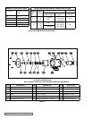
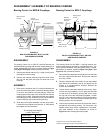
Bearing Carrier for MD2-C Couplings
(Cont.)
.245
.242
Inch
mm
6.223
6.147
Pump Design “A” Dim.
U.S. Inch Design 10.43 inches
Metric Design 265 mm
“C” Coupling Outer Magnet
Location Dimension
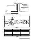
Casing