


SECTION TSM 685.2 ISSUE C PAGE 3 OF 16
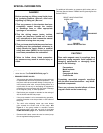
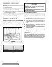
FIGURE 3
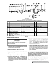
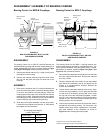
RELIEF VALVE POSITION
SPECIAL INFORMATION
ROTATION: Viking Mag Drive® pumps are designed to run
in either direction. See PUMP ROTATION, page 11.
PRESSURE RELIEF VALVES:
1. Viking pumps are positive displacement pumps and must
be provided with some sort of pressure protection. This
may be a relief valve mounted directly on the pump, an
inline pressure relief valve, a torque limiting device or a
rupture disk. Do not rely on decoupling of magnets for
protection from over pressure; this may result in damage
to the magnets, pump, or other equipment.
2. Relief valves are mounted as standard on the casing of
AS, AK,AL,KE and KKE size pumps.
3. If the pump rotation is to be reversed during operation,
pressure protection must be provided on both sides of
the pump.
4. The relief valve adjusting screw cap must always
point towards the suction side of the pump. See
Figure 3.
If the pump rotation is reversed, remove
the pressure relief valve and turn end for end (see
PUMP ROTATION, page 11 for additional information.
5. Pressure relief valves cannot be used to control pump
flow or regulate discharge pressure.
For additional information on pressure relief valves, refer to
Technical Service Manual TSM000 and Engineering Service
Bulletin ESB-31.
CAUTION !
Rare earth magnets used in couplings have
extremely strong magnetic fields capable of
changing performance or damaging items
such as the following:
Pacemakers
Metal Implants
Watches
Computers & disks
Credit Cards
Completely assembled magnetic couplings
will not affect items listed above – only disas-
sembled components.
There are no known harmful effects of these
magnetic fields on the human body.
RELIEF VALVE ADJUSTING
SCREW CAP
SUCTION
DISCHARGE
DANGER !
Before opening any Viking pump liquid cham-
ber (pumping chamber, reservoir, relief valve
adjusting cap fitting etc.) Be sure:
1. That any pressure in the chamber has been
completely vented through the suction
or discharge lines or other appropriate
openings or connections.
2. That the driving means (motor, turbine,
engine, etc.) has been “locked out” or made
non- operational so that it cannot be started
while work is being done on pump.
3. That you know what liquid the pump has been
handling and the precautions necessary to
safely handle the liquid. Obtain a material
safety data sheet (MSDS) for the liquid to be
sure these precautions are understood.
Failure to follow above listed precaution-
ary measures may result in serious injury or
death.