


SECTION TSM 685.2 ISSUE C PAGE 7 OF 16
6. Remove the idler and bushing assembly. If the idler
bushing needs to be replaced, see “INSTALLATION
OF BUSHINGS” on page 10.
If further disassembly is
required, the pump must be separated from coupling.
Refer to “DISASSEMBLY OF COUPLING” on page 8
before proceeding with Step 7.
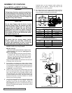
7. With the inner magnet removed, now remove the pump
shaft key. Remove the outer thrust washer. The rotor
and shaft may now be removed by tapping on the end of
the shaft with a soft face hammer (If a soft face hammer
is not available a regular hammer may be used with a
piece of hardwood).
8. Remove the inner thrust washer from behind the rotor.
The casing should be examined for wear, particularly in the
area between the ports. Clean all other parts thoroughly and
examine for wear or damage. Check the bushings, idler pin
and thrust washers; replace if necessary.
When making major repairs, such as replacing a rotor
and shaft, it is advisable to also install a new head and
idler pin, idler and bushing, and casing bushings. See
“INSTALLATION OF BUSHINGS” on page 10.
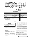
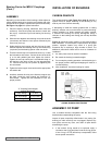
PUMP DISASSEMBLY
1. To drain the liquid being pumped, remove the two (2)
drain plugs located in the bottom of the casing. Once the
liquid has drained replace the plugs.
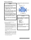
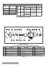
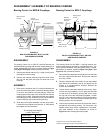
2. Refer to Figures 4, 6, 7 & 8 for names of parts.
3. Mark the head and casing before disassembly to insure
proper reassembly.
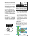
4. To inspect the head and pin assembly and idler and
bushing assembly, remove the head capscrews.
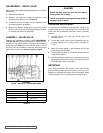
5. Remove the head from the pump. Do not allow the idler
to fall from the idler pin. Tilt the top of the pump head
back when removing to prevent this. Avoid damaging the
head shim set since all shims are required to maintain
end clearance.
WARNING!
Refer to DANGER & CAUTION listed on page 2
before proceeding.
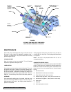
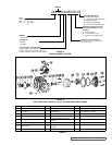
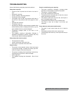
FIGURE 8
ITEM DESCRIPTION ITEM DESCRIPTION ITEM DESCRIPTION
601 Bolt-on Hub with Hardware 611 Bearing Carrier Housing 623 Outer Bearing Spacer
602 Outer Magnet Assembly 613 Drive Key - Outboard Side 624 Tapered Roller Bearing - 2 Req’d
603 Bracket 614 Shaft 625 Lip Seal (Inner)
604
Capscrew (jackscrew) for Disassembly
(metric)
615 Drive Key - Inboard Side 626 Setscrew - 2 Req’d
605 Lifting Eye 617 Inner Bearing Spacer 627 Insert - 2 Req’d
606 Pipe Plug for Sensor Hole 619 Locknut 628 Grease Fitting
607 Capscrews (metric) for Pump - 4 Req’d 620 Lockwasher 629 Adapter (NEMA motor only)
608 Canister and Bushing Assembly 621 End Cap 630
Capscrews (metric) for Adaptor - 4
Required
609 Inner Magnet Assembly 622 Lip Seal (Outer)
610
Capscrews (metric) for Motor or
Bearing Carrier - 4 Req’d (284 Motor
Frame, - 5 req’d)
M DRIVE CONFIGURATION
MD2- C SERIES COUPLING AND BEARING CARRIER COMPONENTS
TABLE 5