


SECTION TSM 685.2 ISSUE C PAGE 13 OF 16
ADJUSTING END CLEARANCE
Table 7-A provides standard operating end clearance
for this pump. Use either of the following procedures to
properly adjust the end clearance when replacing shims or
reassembling the pump.
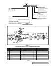
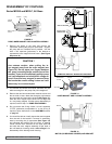
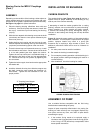
FIGURE 21
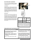
PRESSURE RELIEF VALVE INSTRUCTIONS
Before opening any Viking pump liquid cham-
ber (pumping chamber, reservoir, relief valve
adjusting cap fitting etc.) Be sure:
1. That any pressure in chamber has been
completely vented through suction or
discharge lines or other appropriate openings
or connections.
2. That the driving means (motor, turbine,
engine, etc.) has been “locked out” or made
non- operational so that it cannot be started
while work is being done on pump.
3. That you know what liquid the pump has been
handling and the precautions necessary to
safely handle the liquid. Obtain a material
safety data sheet (msds) for the liquid to be
sure these precautions are understood.
Failure to follow above listed precaution-
ary measures may result in serious injury or
death.
DANGER !
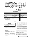
FIGURE 20
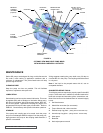
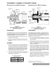
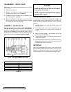
PROCEDURE A
After the rotor has been installed and the locknut has been
positioned and retained, insert a feeler gage of the proper
end clearance thickness into the port at the root (base) of
two rotor teeth (See Figure 20). For convenience, remove
the head O-ring and install one 0.007” shim onto the head.
With the idler on the idler pin, place the head into the pump
casing. With the capscrews tight, the feeler gage should fit
snugly between the idler and the rotor face; otherwise shims
should be added or reduced in thickness until the proper
clearance is attained.
PROCEDURE B
If the pump is in line and ports are not accessible, remove
the head and shims. Put the head back on (without shims)
and measure the gap as shown (See Figure 21). After
determining the gap between the head and casing, select
a combination of shims equal to the measured gap plus
the desired end clearance (See Figure 21). Remove head,
install shims then install head. Tighten the head capscrews
and check the pump clearance by making sure the pump
turns freely by hand. Since the pump shaft is concealed, it
is best to work up to the proper end clearance because it is
difficult to determine when there is too much end clearance
with this approach.
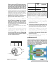
Head
end
Coupling
end
NORMAL
1
END
CLEARANCE
(inch)
SET OF HEAD
SHIMS INCLUDES
AS, AK, AL 855 0.005
(1) .007
(1) .005
(2) .002
(2) .001
KE, KKE 855 0.005
1
End Clearances are adequate for viscosities up to 2500 SSU /
540 cSt (SAE 40 lube oil at room temperature). Higher viscosities
require additional clearances. As a general rule the end clearance
is doubled for higher viscosities. For specific recommendations for
end clearance for viscosity or for operating temperatures above
225 °F (107 °C), check with your Viking representative or consult
the factory.
TABLE 7-A