


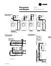

Mechanical
Specifications
CAB-PRC001-EN50
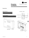
Force–Flo™ Cabinet Heater
Mechanical Specifications
Performance Data
Capacity: Unit capacities are in accor-
dance with Industry Room Fan-Coil Air
Conditioner Certification Program under
ARI Standard 440-97. Safety: All standard
units are UL listed in the United States
and Canada. Units comply with NFPA90A
requirements.
Construction
All Units
The unit includes a chassis, coil, fan
wheel(s), fan casing(s), fan board and
motor(s). The fan board assembly is
easily removable. The fan board assem-
bly includes a quick-disconnect motor
plug. The chassis construction is 18-
gauge galvanized steel, and continuous
throughout the unit. The unit is acousti-
cally and thermally insulated with closed-
cell insulation. All panels are made rigid
by channel forming.
Vertical Cabinet and Slope Top Units
Front panel fabrication is 16-gauge
galvanized steel. All other panels are 18-
gauge galvanized steel. Hinged access
door construction is 20-gauge steel and is
flush with top panel.
Vertical Wall Hung Unit
Front panel fabrication is 16-gauge
galvanized steel. All other panels are 18-
gauge galvanized steel. Side panels are
removable for piping access.
Horizontal Cabinet Units
All panels are 18-gauge galvanized steel,
including the bottom panel. The hinged
access door is flush with front panel.
Bottom panels ship with tamperproof
screw fasteners and safety chain.
Concealed/Recessed Units
Exposed panels on recessed units are 18-
gauge steel construction and ship
separate from the unit. Bottom panels on
horizontal recessed models ship with
tamperproof screw fasteners and safety
chain.
Unit Finish
All cabinet parts and exposed recessed
panels are cleaned, bonderized, phos-
phatized, and painted with a baked
powder finish available in six decorator
colors. Standard finish meets ASTM B117
specifications (salt spray test).
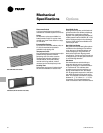
Fans
The aluminum fan wheels are centrifugal
forward-curved and double-width. Fan
wheels and housings are corrosion
resistant. Fan housing construction is
formed sheet metal.
Motors
All permanent split capacitor motors are
run tested in assembled units. All motors
have integral thermal overload protection
with a maximum ambient operating
temperature of 104 F and are perma-
nently lubricated. Motors are capable of
starting at 78 percent of rated voltage and
operating at 90 percent of rated voltage
on all speed settings. Motors can operate
up to 10 percent over voltage.
Hot Water Coils
Hot water coils are burst tested at 450
psig (3,103 kPa) (air) and leak tested at
100 psig (690 kPa) (air under water).
Maximum main coil working pressure is
300 psig (2,069 kPa). Maximum entering
water temperature is 200 F (93 C). Tubes
and u-bends are
3
/
8
”(10 mm) OD copper.
Fins are aluminum and are mechanically
bonded to the copper tubes. Coil
stubouts are
5
/
8
”(16 mm) OD copper
tubing.
Steam Coils
The steam heating coil is a one-row, tube-
in-tube distributing type coil. Coil con-
struction is aluminum fins mechanically
bonded with 1” (25 mm) OD copper
tubing. Steam coils are (air) burst tested
at 250 psig (1,724 kPa). Maximum steam
coil working pressure is 100 psig (689
kPa). Maximum entering steam tempera-
ture is 325 F (163 C). Tubes and u-bends
are
5
/
8
” (16 mm) OD copper. Fins are
aluminum, 9 fpi, and are mechanically
bonded to the copper tubes. Coil
stubouts are 1” (25 mm) OD copper
tubing. Piping is field-supplied.
Piping Packages (Hot Water Coils Only)
All piping packages are burst tested at
450 psig (3,103 kPa) (air) and leak tested
at 100 psig (690 kPa) (air under water).
The maximum working pressure of the
interconnecting piping is 300 psig (2,069
kPa).
Piping packages are available in either
basic or deluxe configurations. The
deluxe package includes unions at the coil
connections and a 20 mesh strainer on
the supply side with a pressure rating on
the strainer of up to 400 psig (2,758 kPa).
The basic package does not include either
unions or the strainer.
End valve options available on both the
basic and deluxe piping packages
include ball valves, manual circuit setters,
and auto circuit setters.
Ball Valve Supply and Return
A ball-type stop valve is on the piping
supply and return. The ball valve is a
shutoff valve only with a maximum
working pressure of 400 psig (2,758 kPa).
Ball Valve Supply, Manual Circuit Setter
Return
A ball valve is provided on the supply
with a manual circuit setter on the return.
The manual circuit setter is a combina-
tion flow-setting device and shutoff valve
that includes two Schrader ports. The
maximum working pressure of the valve
is 300 psig (2,069 kPa).
Ball Valve S & R, Auto Circuit Setter
Return
Ball type end valves are mounted on the
supply and return, with an additional
auto circuit setter mounted on the return.
The auto circuit setter is an automatic
flow control valve that is sized to allow a
specific GPM through the coil. Auto
circuit setters also include two P/T plugs
and have a maximum working pressure
of 400 psig (2,758 kPa).
Two-Way, Two-Position Control Valves
When using two-way valves, use some
means such as a pump and chiller bypass
to ensure the maximum closed off DP
rating of the valve is not exceeded. Two-
way, two-position valves are rated for a
maximum pressure differential across
the valves of 25 psig (172 kPa). The
valves are also available with a close-off
pressure of 50 psig (345 kPa). The valve
actuator is easily removable for service
without removing the valve body from
piping.