


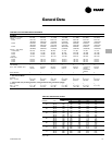
Selection
Procedure
CAB-PRC001-EN 5
Digit 20 — Coil Air Vent
A = Automatic Air Vent
M= Manual Air Vent
Digits 21, 22, 23 — Electric Heat kW
(208V Derate)
000 = No Electric Heat
010 = 1.0 kW (0.75 kW)
020 = 2.0 kW (1.5 kW)
030 = 3.0 kW (2.3 kW)
045 = 4.5 kW (3.3 kW)
060 = 6.0 kW (4.5 kW)
075 = 7.5 kW (5.7 kW)
090 = 9.0 kW (6.6 kW)
100 = 10.0 kW
105 = 10.5 kW (7.9 kW)
110 = 11.0 kW (9.0 kW)
120 = 12.0 kW
135 = 13.5 kW (10.2 kW)
150 = 15.0 kW
180 = 18.0 kW (13.5 kW)
200 = 20.0 kW (15.0 kW)
Digit 24 —Not Used
Digit 25 — Disconnect Switch
0 = None
D = Disconnect Switch
Digit 26 — Filter
0= None
1= 1” Throwaway Filter
2= 1” Throwaway Pleated Media Filter
3= 1” Throwaway + (1) Extra
4=
1” Throwaway Pleated Media + (1)
Extra
5= 1” Throwaway + (2) Extras
6= 1” Throwaway Pleated Media +
(2) Extras
7= 1” Throwaway + (3) Extras
8= 1” Throwaway Pleated Media +
(3) Extras
Digits 1, 2 — Unit Type
FF = Force–Flo
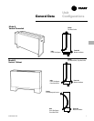
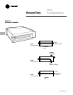
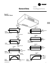
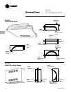
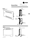
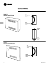
Digit 3 — Cabinet Type
A = Vertical Concealed
B = Vertical Cabinet
C = Horizontal Concealed
D = Horizontal Cabinet
E = Horizontal Recessed
H = Vertical Recessed
J = Vertical Cabinet Slope Top
M = Inverted Vertical Cabinet
N = Inverted Vertical Recessed
Digit 4 — Development Sequence “B”
Digits 5, 6, 7 — Unit Size
020 040 080
030 060 100
120
Digit 8 — Unit Voltage
1 = 115/60/1 6 = 230/60/3
2 = 208/60/1 7 = 480/60/3
3 = 277/60/1 8 = 110-120/50/1
4 = 230/60/1 9 = 220-240/50/1
5 = 208/60/3 A = 220-240/50/3
B = 380-415/50/3
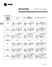
Digit 9 — Piping System/Placement
A = No piping, RH
B = No piping, LH
E = No piping, RH,Extended End Pocket
F = No piping, LH, Extended End Pocket
J = With piping package, RH
K = With piping package, LH
L = With piping package, RH, Extended
End Pocket
M= With piping package, LH, Extended
End Pocket
Digits 10, 11 — Design Sequence “M0”
Digit 12 — Inlets
A = Front Toe Space
B = Front Bar Grille
C = Front Stamped Louver
D = Bottom Stamped Louver
E = Bottom Toe Space
F = Back Duct Collar
G = Back Open Return
H = Back Stamped Louver
J = Top Duct Collar
FF B B 020 1 C M0 A 0 G 1 0 A A 2 M 000 0 0 1 0 0 0 A A 000 000 0 0 0 0 0 0 0
1 5 10 15 20 25 30 35 40 44
Digit 13 — Fresh Air Damper
0 = None
A = Manual, Bottom Opening
B = Manual, Back Opening
C = Manual, Top Opening
K = No Damper, Bottom Opening
L = No Damper, Back Opening
M= No Damper, Top Opening
Digit 14 — Outlets
A = Front Duct Collar
B = Front Bar Grille
C = Front Stamped Louver
D = Front Quad Grille
E = Bottom Duct Collar
F = Bottom Stamped Louver
G = Top Quad Grille
H = Top Bar Grille
J = Top Duct Collar
Digit 15 — Color
0 = No Paint (Concealed Units Only)
1 = Deluxe Beige 4 = Driftwood Grey
2 = Soft Dove 5 = Stone Grey
3 = Cameo White 6 = Rose Mauve
Digit 16 —
Tamperproof Locks/Leveling
Feet
0 = None
B = Keylock Access Door
C = Keylock Panel and Access Door
D = Leveling Feet
F=
Keylock Access Door with Leveling
Feet
G = Keylock Panel and Access Door with
Leveling Feet
Digit 17 — Motor
A = Free Discharge
B = High Static
Digit 18 — Coil
A = 2 Row Hot Water
B = 3 Row Hot Water
C = 4 Row Hot Water
N = Electric Heat, Single Stage
U = Electric Heat, Two Stage
V = Electric Heat, Low kw, One Stage
W = Steam Distributing
Digit 19 — Coil Series
1 = 108 fpf (steam only)
2 = 144 fpf (hot water only)
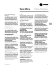
Force–Flo Cabinet Heater Model Number Description
Following is a complete description of the cabinet heater model number. Each digit in the model number has a corresponding
code that identifies specific unit options.
Model Number
Description