


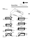
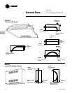
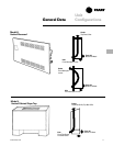
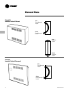
General Data
CAB-PRC001-EN 17
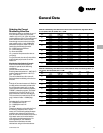
Selecting the Correct
Modulating Valve Size
Modulating valves are available in any of
four port sizes. These four port sizes
relate to a Cv of 0.7, 1.5, 2.5 or 4.0, which
is the coefficient of flow. The coefficient of
flow is defined as the volume of water
flow through a control valve in the fully
open position with a 1 psig (6.895 kPa)
differential across the valve. It is calcu-
lated using the following formula:
Cv = Q/Square root ∆P where:
Cv = flow coefficient
Q = flow rate (GPM)
∆P = pressure drop across the valve or
coil (psig).
For good control, the valve Cv should be
approximately equal to the Cv of the
water coil.
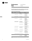
Modulating Valve Selection Example
Assume a size 06 cabinet heater is
selected to operate at the following
conditions:
Vertical cabinet cabinet heater
Entering water temperature = 180 F (82 C)
Leaving water temperature = 150 F ( C)
EAT = 70 F (21 C)
The coil is selected as a four-row coil.
Select the best modulating valve size for
this unit.
1
Find the ∆P across the water coil. Refer to
the ARI performance table to determine
the ∆P across the water coil or use the
Trane Official Product Selection System,
TOPSS™, selection program. The water
pressure drop is found to be 5.7’ (17.0
kPa) of water at a flow rate of 3.59 gpm.
This converts to a pressure drop of 2.47
psig (1.0 feet of water = 0.4328 psig.)
2
Calculate the Cv of the water coil.
Cv = GPM/Square root ∆P.
Cv = 3.59/Square root 2.47
Cv = 2.29
Therefore, select the valve with the Cv of
2.5 since it is closest to the Cv of the
water coil. The following tables illustrate
possible valve selections at ARI condi-
tions for horizontal concealed units with a
high static motor and vertical cabinet
units with a free discharge motor. For
other applications, use TOPSS to
determine the flowrate and make
calculations using the formulas above.
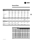
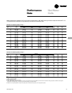
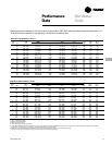
Table GD-3. Modulating Valve Selections for Horizontal Concealed Units, High Static Motor,
70 F (21 C) EAT, 180 F (82 C) EWT, 30 F (-1 C)
∆∆
∆∆
∆
T
Unit Coil Coil Valve
Size Coil GPM (L/s) WPD (kPa) Cv Cv
2-Row 1.19 (0.08) 6.0 (17.8) 0.74 0.7
02 3-Row 1.52 (.10) 13.8 (41.2) 0.62 0.7
4-Row 1.59 (.10) 3.8 (11.5) 1.24 1.5
2-Row 1.53 (.10) 10.3 (30.8) 0.72 0.7
03 3-Row 1.82 (.11) 4.3 (12.8) 1.33 1.5
4-Row 1.98 (.12) 6.2 (18.6) 1.21 1.5
2-Row 1.73 (.11) 3.3 (9.8) 1.45 1.5
04 3-Row 2.57 (.16) 9.1 (27.0) 1.29 1.5
4-Row 2.81 (.18) 13.4 (39.9) 1.17 1.5
2-Row 2.87 (.18) 9.9 (29.5) 1.39 1.5
06 3-Row 3.96 (.25) 5.9 (17.7) 2.48 2.5
4-Row 4.37 (.28) 8.2 (24.6) 2.32 2.5
2-Row 3.71 (.23) 4.7 (14.2) 2.60 2.5
08 3-Row 4.74 (.30) 9.1 (27.1) 2.39 2.5
4-Row 5.22 (.33) 12.7 (37.8) 2.23 2.5
2-Row 4.71 (.30) 8.1 (24.1) 2.52 2.5
10 3-Row 6.50 (.41) 18.1 (54.0) 2.32 2.5
4-Row 7.13 (.45) 25.3 (75.6) 2.15 2.5
2-Row 5.48 (.35) 11.4 (34.0) 2.47 2.5
12 3-Row 7.19 (.45) 14.5 (43.2) 2.87 2.5
4-Row 7.83 (.51) 10.5 (31.4) 3.67 4.0
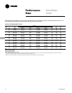
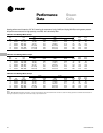
Table GD-4. Modulating Valve Selections for Vertical Cabinet Units, Free Discharge Motor, 70
F (21 C) EAT, 180 F (82 C) EWT, 30 F (-1 C)
∆∆
∆∆
∆
T
Unit Coil Coil Valve
Size Coil GPM (L/s) WPD (kPa) Cv Cv
2-Row 1.06 (.07) 4.8 (14.4) 0.74 0.7
02 3-Row 1.31 (.08) 10.5 (31.4) 0.61 0.7
4-Row 1.34 (.08) 2.8 (8.4) 1.22 1.5
2-Row 1.40 (.09) 8.8 (26.3) 0.72 0.7
03 3-Row 1.70 (.11) 3.8 (11.3) 1.33 1.5
4-Row 1.81 (.11) 5.3 (15.7) 1.20 1.5
2-Row 1.71 (.11) 3.2 (9.5) 1.45 1.5
04 3-Row 2.12 (.13) 6.4 (19.0) 1.27 1.5
4-Row 2.28 (.14) 9.1 (27.3) 1.15 1.5
2-Row 2.70 (.17) 8.9 (26.5) 1.38 1.5
06 3-Row 3.31 (.21) 4.2 (12.6) 2.46 2.5
4-Row 3.59 (.23) 5.7 (17.0) 2.29 2.5
2-Row 3.39 (.21) 4.0 (11.9) 2.58 2.5
08 3-Row 4.11 (.26) 6.9 (20.7) 2.38 2.5
4-Row 4.45 (.28) 9.4 (28.1) 2.21 2.5
2-Row 4.32 (.27) 6.8 (20.4) 2.52 2.5
10 3-Row 5.55 (.35) 13.4 (40.2) 2.30 2.5
4-Row 6.00 (.38) 18.3 (54.8) 2.13 2.5
2-Row 4.99 (.32) 9.6 (28.6) 2.45 2.5
12 3-Row 6.10 (.38) 10.5 (31.4) 2.86 2.5
4-Row 6.48 (.42) 7.3 (21.8) 3.65 4.0