


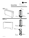
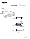
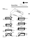
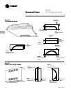
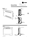
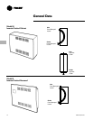
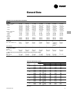
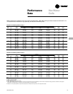
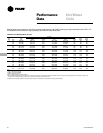
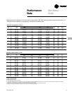
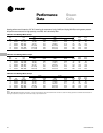
General Data
CAB-PRC001-EN 15
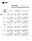
Factory-Installed Piping
Packages
Force–Flo cabinet heaters have standard
piping packages available as a factory
built and installed option. Factory built
assures all piping packages are fully
tested under water for leaks and are built
within strict tolerances. Factory-installed
means that supply and return pipes are
the only field connections required. The
installer doesn’t have to sweat connect
piping packages onto coil connections in
a tight end pocket. Field connections are
brought to a point near the exterior of the
unit for easy access.
Piping Package Components
Force–Flo piping packages consist of a
variety of components for each applica-
tion. The following section provides a
detailed description of the piping compo-
nents. Following this section are addi-
tional illustrations and specifications.
Piping System/Placement
Factory piping packages are available
with right or left hand connections. A
simple coil connection (a unit without a
piping package) is also available in either
a right or left hand configuration for those
applications requiring field piping.
Interconnecting Piping
Interconnecting piping refers to the
copper piping which is attached to the
coil connections and all other compo-
nents such as control valves, end valves,
etc. Piping is
1
/
2
” nominal OD copper and
extends near the unit exterior to one inlet
and one outlet connection.
Deluxe or Basic Piping Package
The basic piping package includes only
the main components of the piping
package: interconnecting piping, control
valves, and end valves.
The deluxe piping package also includes
a strainer on the entering water pipe and
unions at the coil connections along with
the basic components. The strainer body
is cast brass construction, with a stain-
less steel mesh strainer that is easily
removed for cleaning. The unions are
forged brass construction and close with
a minimum amount of effort.
End Valves
Each piping package includes a ball valve
for the entering water pipe and one of the
following end valves on the leaving water
pipe: ball valve, manual circuit setter, or
an auto circuit setter. These valves serve
as the field connection points on all
Force–Flo piping packages.
• Ball Valves
Ball valves, also known as stop or end
valves, allow the unit to be cut off for
service purposes. These valves have a
two-inch handle that rotates 90 degrees
to a fully open position. The valve body is
cast brass, and the ball is polished brass
with a Teflon seat. Ball valves are available
as end valves on both the entering and
leaving water pipes.
Manual Circuit Setter
In lieu of a ball valve on the leaving water
pipe, a manual circuit setter, also known
as a manual flow control valve, acts as
both a flow setting device and a stop
valve. This valve allows water flow
through the cabinet heater to be set
quickly and accurately.
The manual circuit setter includes
Schrader ports in the valve body. These
ports are used to measure the pressure
drop across the valve. This pressure drop
can be compared to factory supplied
curves that relate the pressure drop to a
specific flow rate. This valve also has a
memory stop so the correct setting can
be found quickly.
Auto Circuit Setter
An auto circuit setter is an automatic flow
control device available on the leaving
water pipe. The auto circuit setter
includes a cartridge within the valve body
that is sized to allow a specific flow rate
through the coil. This valve sets flow
through the coil without any action
required by a system piping balancer. The
auto circuit setter is available on the
leaving water pipe with a ball valve.
The auto circuit setter also includes two
P/T’s plugs in the valve body to allow
measurement of the pressure drop
temperature through the valve.
Control Valves
Piping packages are available with or
without control valves. All control valve
options are factory mounted and wired to
the Force–Flo unit controls.
Piping Packages
• Two-Way/Two-Position Valves
These valves will either fully open or
close in response to a 24VAC signal from
the Trane controller. Control valves are
direct-acting valves. The control valve is
factory mounted in the leaving water pipe
downstream of the coil. Some means of
relieving pump head pressure should be
accounted for when two-way valves are
selected. Normally open or normally
closed valves are available.
• Three-Way/Two-Position Valves
These valves will either allow full water
flow through the coil or divert the flow
through a bypass line. The valves
respond to a 24VAC signal from the Trane
controller. Control valves are direct acting
valves. All three-way valve packages
include a balance fitting in the bypass line
to allow flow balancing in the bypass
position. Three-way valves are factory
mounted in the leaving water pipe
downstream of the coil. Normally open
or normally closed valves are available.
• Two-Way Modulating Valves
These valves modulate the water flow
through the coil in response to a signal
from the Trane controller. Modulating
valves are three-wire floating point equal
percentage valves, and are factory
mounted in the leaving water pipe
downstream of the coil.
• Three-Way Modulating Valves
These valves modulate the water flow
through the coil in response to a signal
from the Trane controller. Three-way
valves allow water that is directed
through the coil to mix with water that is
directed through the bypass line. This
mixture exits through the leaving water
pipe. Modulating valves are three-wire
floating point equal percentage valves,
and are factory mounted in the leaving
water pipe downstream of the coil.