


Toshiba
–20–
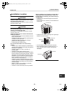
Outdoor Unit
Installation Manual
EN
12TROUBLESHOOTING
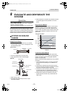
You can perform fault diagnosis of the outdoor unit with the LEDs on the P.C. board of the outdoor unit in addition
to using the check codes displayed on the wired remote controller of the indoor unit.
Use the LEDs and check codes for various checks. Details of the check codes displayed on the wired remote
controller of the indoor unit are described in the Installation Manual of the indoor unit.
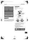
Verifying Fault code status (Outdoor control
board)
1. Check that DIP switch SW803 is set to off.
2. Record the states (on or off) of LED 800 to LED 804
(Display mode 1).
3. Press SW800 for at least 1 second. The LED status
changes to display mode 2.
4. Since display mode 1 covers multiple faults with the
same code display, mode 2 must also be used to
determine the final fault. Use the status recorded for
LED 800 to LED 804 in display mode 1 (Item 2
above) and combine it with the status for the same
LED’s in display mode 2 (Item 3 above) to determine
the complete fault code using the chart below.
Verifying Fault code status stored in
memory (Outdoor control board)
1. Check that DIP switch SW803 is set to on.
2. Record the states (on or off) of LED 800 to LED 804
(Display mode 1).
3. Press SW800 for at least 1 second. The LED status
changes to display mode 2.
4. Since display mode 1 covers multiple faults with the
same code display, mode 2 must also be used to
determine the final fault. Use the status recorded for
LED 800 to LED 804 in display mode 1 (Item 2
above) and combine it with the status for the same
LED’s in display mode 2 (Item 3 above) to determine
the complete fault code using the chart below.
NOTE
An outside air temperature (TO) sensor error can be
checked only when an error occurs.
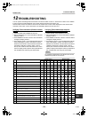
No. Cause
Display mode 1 Display mode 2
D800 D801 D802 D803 D804 D800 D801 D802 D803 D804
1Normal
●●●●●●●●●●
2 Discharge (TD) sensor error
{{●●{ ●● ●●
3 Heat exchanger (TE) sensor error
{{●●{ ●●●
4 Heat exchanger (TL) sensor error
{{●●{ ●●
5 Outside air temperature (TO) sensor error
{{●●{ ●●● ●
6 Suction (TS) sensor error
{{●●{ ●● ●
7 Heat sink (TH) sensor error
{{●●{ ●●
8
Outdoor temperature sensor (TE/TS) connection
error
{{●●{ ●
9 Outdoor EEPROM error
{{●●{
10 Compressor lock
●●{ ● { ●●●●
11 Compressor lock
●●{ ● { ●●●●
12 Current detection circuit error
●●{ ● { ●●●
13 Thermostat for compressor activated
●●{ ● { ●● ●●
14
Model data not set
(on the service P.C. board)
● {{● { ●●●
15 MCU-MCU communication error
● {{● { ●
16
Discharge temperature error
{{{● { ●●●
17
Abnormal power
(open phase detected or abnormal voltage)
{{{● { ●●●
18 Heat sink overheat
{{{● { ●●
19 Gas leak detected
{{{● { ●
20 4-way valve reverse error
{{{● { ●●
(●:OFF {:ON :Flashing)
20-EN
+00EH99865401_00Ta.book Page 20 Wednesday, November 25, 2009 11:19 AM