


Toshiba
–17–
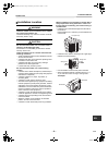
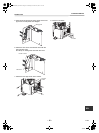
Outdoor Unit
Installation Manual
8 EVACUATE AND DEHYDRATE THE
SYSTEM
CAUTION
UNIT DAMAGE HAZARD
Failure to follow this caution may result in equipment
damage or improper operation.
Never use the system compressor as a vacuum pump.
Refrigerant tubes and indoor heat exchanger should
be evacuated using the recommended deep vacuum
method of 500 microns. The alternate triple evacuation
method may be used if the procedure outlined below is
followed. Always break a vacuum with dry nitrogen.
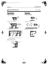
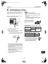
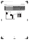
SYSTEM VACUUM AND
CHARGE
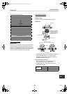
Using Vacuum Pump
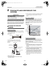
1. Completely tighten flare nuts A, B, C, D, connect
manifold gage charge hose to a charge port of the
low side service valve.
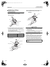
2. Connect charge hose to vacuum pump.
3. Fully open the low side of manifold gage.
4. Start vacuum pump.
5. Evacuate using either deep vacuum or triple
evacuation method.
6. After evacuation is complete, fully close the low side
of manifold gage and stop operation of vacuum
pump.
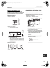
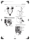
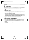
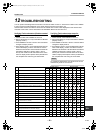
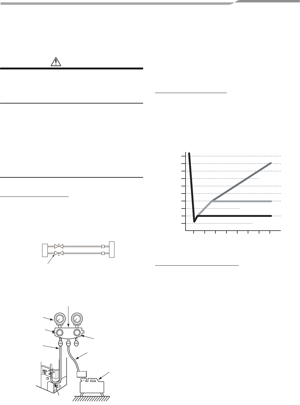
Deep Vacuum Method
The deep vacuum method requires a vacuum pump
capable of pulling a vacuum of 500 microns and a
vacuum gage capable of accurately measuring this
vacuum depth. The deep vacuum method is the most
positive way of assuring a system is free of air and
liquid water.
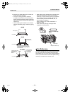
Triple Evacuation Method
The triple evacuation method should only be used
when vacuum pump is only capable of pumping down
to 28 in. of mercury vacuum and system does not
contain any liquid water.
Refer to “Triple Evacuation Method chart” and proceed
as follows:
1. Pump system down to 28 in. of mercury and allow
pump to continue operating for an additional 15
minutes.
2. Close service valves and shut off vacuum pump.
3. Connect a nitrogen cylinder and regulator to system
and open until system pressure is 2 psig.
4. Close service valve and allow system to stand for 1
hr. During this time, dry nitrogen will be able to
diffuse throughout the system absorbing moisture.
5. Repeat this procedure as indicated in the chart.
System will then be free of any cotaminants and
water vapor.
Service Valve
Indoor Unit
C
D
A
B
Refrigerant
Low Side
High Side
Outdoor Unit
Service Valve
Manifold
500 microns
Manifold Gage
Low side valve
Charge hose
High side valve
Charge hose
Vacuum pump
Low side valve
500
0
1000
1500
2000
2500
3000
3500
4000
4500
5000
1 2 3 4 5 6 7
LEAK IN
SYSTEM
VACUUM TIGHT
TOO WET
TIGHT DRY
SYSTEM
Deep Vacuum Graph
MICRONS
MINUTES
17-EN
+00EH99865401_00Ta.book Page 17 Wednesday, November 25, 2009 11:19 AM