


Toshiba
–12–
Outdoor Unit
Installation Manual
EN
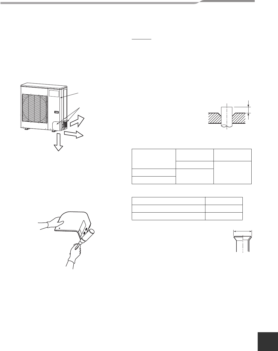
6 REFRIGERANT PIPING
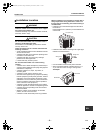
Piping connections are inside the front panel of the unit
and the front panel and pipe cover needs to be
removed before piping and wiring connections are
made.
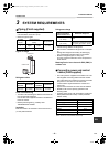
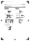
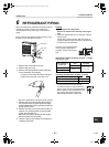
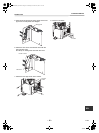
Piping can enter the outdoor unit from the back, from
the side or from the bottom as shown
1. Remove the front panel of the unit.
2. Remove the pipe cover.
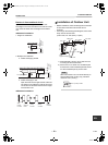
3. Remove the appropriate knockout depending
on the orientation of the piping.
* Be sure to wear heavy work gloves while working.
4. Remove the burrs from the knockout opening
and use the factory supplied protective edge
guard material around the opening to protect the
piping and the wiring.
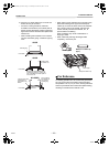
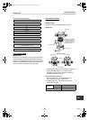
5. Remove the flare nut from the service valve on
outdoor unit. Insert the flare nut into the field
piping, and flare the pipe.
Bend the pipe approx. 90 degree with a pipe
bender for side and rear piping.
6. When the piping connections are complete re-
install the pipe cover.
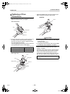
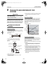
Flaring
1. Cut the pipe with a pipe cutter.
Be sure to remove burrs that may cause a gas
leak.
2. Insert the supplied flare nut into the pipe, and then
flare the pipe.
As the flaring sizes of R410A differ from those of
refrigerant R22, the flare tools newly manufactured
for R410A are recommended.
However, the conventional tools
can be used by adjusting the
projection margin of the copper
pipe.
▼ Projection margin in flaring : B (Unit : in (mm))
Rigid (Clutch type)
▼ Flaring diameter size : A (Unit : in (mm))
* In case of flaring for R410A with the
conventional flare tool, pull the tool out
approx. 0.02” (0.5 mm) more than that for
R22 to adjust it to the specified flare size.
The copper pipe gauge is useful for
adjusting the projection margin size.
Rearward
Pipe cove
r
Sideward
Downward
Rear
Front panel
Side
Bottom
Pipe cover
The pipe cover is easily mounted by cutting off
the slit at the lower part of the pipe cover.
Outer diameter of
copper pipe
R410A tool
used
Conventional
tool used
R410A
0.04” - 0.06”
(1.0 - 1.5)
3/8” (9.5)
0 - 0.02” (0 - 0.5)
5/8” (15.9)
Outer diameter of copper pipe A
3/8” (9.5) 0.52” (13.2)
5/8” (15.9) 0.78” (19.7)
B
+0
-0.02" (–0.4)
A
12-EN
+00EH99865401_00Ta.book Page 12 Wednesday, November 25, 2009 11:19 AM