


Toshiba
–10–
Outdoor Unit
Installation Manual
EN
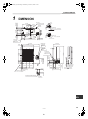
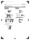
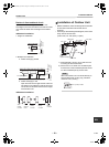
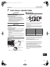
Barriers in front and back of unit
Open above and to the right and left of the unit.
The height of an barrier in both the front and rear of the
unit, should be lower than the height of the outdoor
unit.
▼ Standard installation
1. Single unit installation
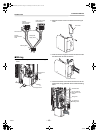
2. Multiple unit installation
a. Intake and supply parallel
b. Intake and supply in line
Open above and to the right and left of the unit.
The height of an obstacle in both the front and
rear of the unit should be lower than the height
of the outdoor unit.
▼ Standard installation
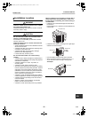
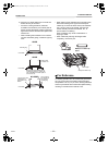
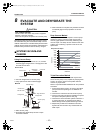
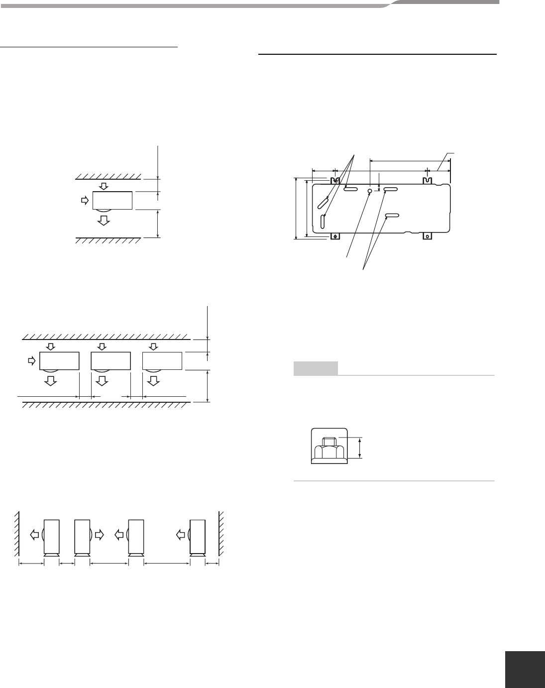
Installation of Outdoor Unit
• Before installation, check the strength and horizontal
of the base so that abnormal sounds do not
emanate.
• According to the following base diagram, fix the base
firmly with the anchor bolts.
(Anchor bolt, nut: 3/8” (M10) x 4 pairs)
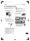
1) Field fabricate a snow or an ice stand for the
unit using the above dimension.
2) Place snow or ice stand on a foundation/pad
and secure it to the foundation/pad and secure
it to the foundation/pad by anchor bolts.
5.9” (150)
or more
39.4” (1000)
or more
11.8” (300) or more
11.8” (300)
or more
39.4” (1000)
or more
7.9” (200)
or more
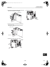
39.4”
(1000)
or more
11.8”
(300) or
more
59.1”
(1500)
or more
78.7”
(2000)
or more
7.9”
(200)
or more
Drain hole
Drain
nipple mounting hole
Drain hole
5.9” (150)
20.7” (525)
1.8” (45)
23.6” (600)
15.8” (400)
14.4” (365)
5.9” (150)
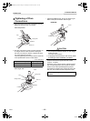
NOTE
When the outdoor unit is anchored directly on
the foundation/pad (cooling only protrude a
minimum of 6” (15 mm)).
0.6” (15 mm) or less
10-EN
+00EH99865401_00Ta.book Page 10 Wednesday, November 25, 2009 11:19 AM