


Toshiba
–14–
Outdoor Unit
Installation Manual
EN
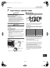
7 ELECTRICAL CONNECTIONS
WARNING
ELECTRICAL SHOCK HAZARD
Failure to follow this warning could result in
personal injury or death.
• The unit cabinet must have an uninterrupted or
unbroken ground to minimize personal injury if an
electrical fault should occur. The ground may consist
of electrical wire or metal conduit when installed in
accordance with existing electrical codes.
• Before performing service or maintenance, be sure
main power switch is turned OFF.
CAUTION
All wiring and connections must comply with NEC, CEC,
local codes.
UNIT DAMAGE HAZARD
Failure to follow this caution may result in damage
or improper operation.
• Unit failure as a result of operation on improper line
voltage or excessive phase imbalance constitutes
abuse and may cause damage to electrical
components.
• Wrong wiring may cause a burn-out of some electrical
parts.
• Do not damage or scratch the conductive core or inner
insulator of the power and inter-connecting wires
when peeling them.
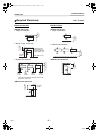
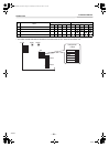
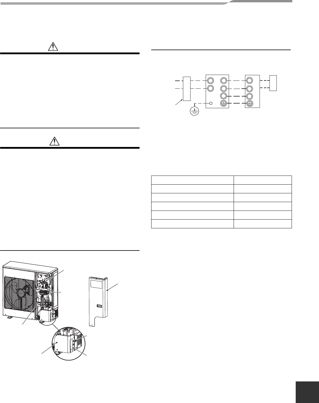
Field wiring
The dashed lines show field wiring.
• System interconnection wire size must be AWG12.
• Breaker must have a capacity specified in the
following table.
• All wiring must comply with local electric codes and
NEC (National Electric Code) or CEC (Canadian
Electric Code).
• Connect the system interconnection wires (indoor to
outdoor) to the identical terminal numbers on the
terminal block of each unit.
Incorrect connection may cause a failure.
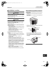
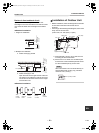
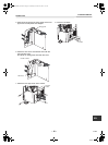
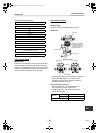
1. With the front panel removed the electrical control
box is exposed at the top right corner of the unit.
2. Terminate the field wiring conduit (if used) at the
conduit connection holes provided.
3. Route the field power wires and the system
interconnection wires as shown on the following
pages. Terminate the wires at field wiring terminal
blocks located immediately below the electrical
control box.
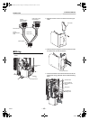
Electric parts box
Conduit connection
holes
Piping knockout
Pipe cover
Front pane
Electric control box
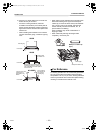
Field wiring
terminal
blocks
Conduit connection
holes
Front panel
Piping knockout
Front Pipe cover
Valve mounting
bracket
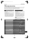
Model RAV- SP240
Power supply 208/230 V, 60 Hz
MCA 24 A
MOCP (MAX Fuse/CB) 40 A
Breaker 25 A
System interconnection wires AWG12
MCA = Minimum Circuit Amps
MOCP =Maximum Over Protection Device Amps.
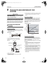
L
1
L
2
L
1
L
2
S
L
1
L
2
S
Input
power
(Field power
supply)
(System
interconnection wires)
ground
Outdoor unit Indoor unit
Remote
controller
circuit breaker
208/230 V~,
60 Hz
14-EN
+00EH99865401_00Ta.book Page 14 Wednesday, November 25, 2009 11:19 AM