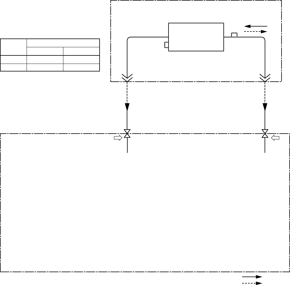
3. SYSTEMATIC REFRIGERATING CYCLE DIAGRAM
3-1. Hi Wall type
RAV-SM562KRT-E/SM802KRT-E
NOTE :
The refrigerating cycle differs according to the combined outdoor units.
For the cycle diagram, cycle pressure, etc., refer to the following Service Manual.
RAV-SMXXX0AT-E : A03-007
RAV-SPXXXXAT-E : A03-014
Indoor unit
Outdoor unit
Outer diameter of refrig erant pipeModel
RAV-SM
Gas side ØA Liquid side ØB
12.7 mm 6.4 mm
15.9 mm
9.5 mm
TCJ
sensor
Air heat exchanger
TC sensor
Refrigerant pipe
at gas side
Outer dia. ØA
562KRT-E
802KRT-E
Refrigerant pipe
at liquid side
Outer dia. ØB
Packed valve
Outer dia. ØA
Pd PsPacked valve
Outer dia. ØB
Cooling
Heating
RAV-SMXXX1AT-E : A05-001
– 5 –


