Troubleshooting (Continued)
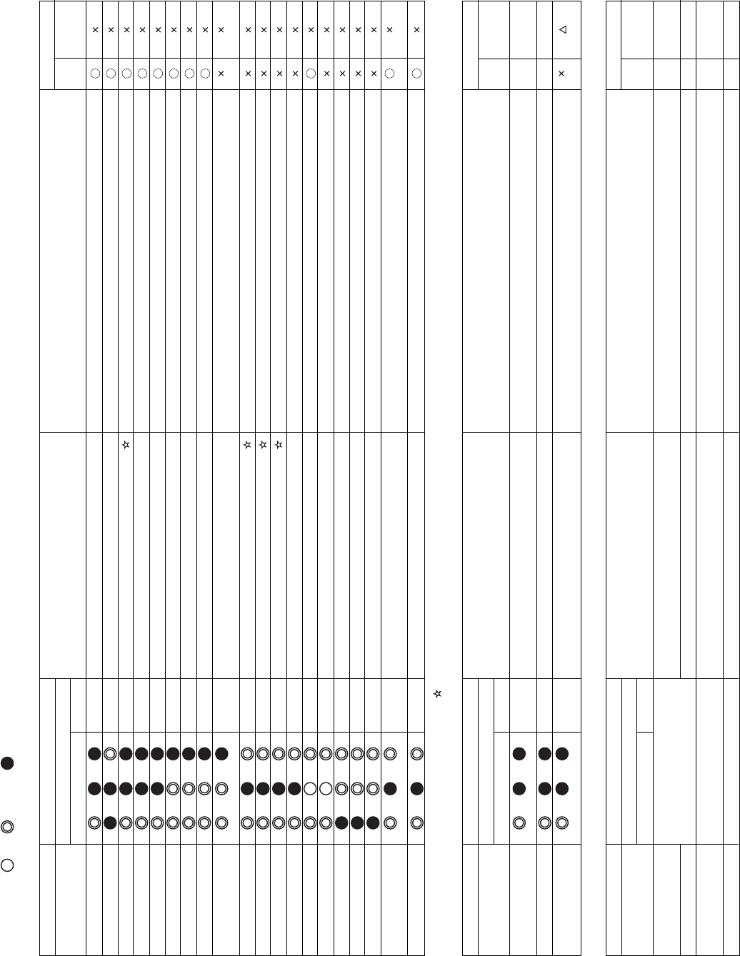
Check Code Table (Indoor Unit)
Check code
TCC-LINK central control
and remote controller
E03
E04
E08
E10
E18
F01
F02
F10
F29
L03
L07
L08
L09
L20
L30
P01
P10
P12
P19
P31
A/C operation
Auto
reset
Operation
continuation
:When this alarm is detected before checking group configuration and address at power on, the unit enters auto address setting mode automatically.
Lamp indication
Block indication
OPERATION TIMER PREPARING
Blinking
Main faulty location
Indoor unit – R/C communication error
Indoor unit – out door unit serial communication error
Duplication of indoor unit address
Communication error between indoor unit MCUs
Communication error between header and follower indoor units
Indoor unit heat exchange sensor TCJ
Indoor unit heat exchange sensor TC
Indoor unit room temp. sensor TA
Indoor unit other boards
Duplication of indoor group header unit setting
Group line in individual indoor unit
Indoor group address not set
Indoor unit capacity not set
Duplication of central control refrigerant line address
External alarm input into indoor unit (interlock)
Indoor unit AC fan
Indoor unit water overflow
Indoor unit DC fan
Four-way valve system
Other indoor unit errors
Description of failures
No signal from remote controller (no communication with central controller system)
When indoor unit – out door unit serial communication is abnormal
When same address as mine is detected
When communication between main motor microcomputers is abnormal
When communication between header and follower indoor units is disabled
When open-circuit or short-circuit of TCJ is detected
When open-circuit or short-circuit of TC is detected
When open-circuit or short-circuit of TA is detected
Failure of EEPROM (Other errors are also detected in some cases.
Auto address repeated with no other errors.)
When multiple header units exist in the group
When there is at least one group connection indoor unit in individual indoor unit
When indoor group address is not set
Indoor unit capacity is not set.
Duplicated central control refrigerant line address is set.
Alarm stop by external alarm input (CN80)
When indoor unit AC fan alarm is detected (Fan motor thermal relay is activated.)
When float switch is turned on
When indoor unit DC fan alarm (overcurrent, locking, etc.) is detected
When an alarm is detected during heating due to temperature drop of
heat exchange sensor
Follower units in the group are disabled due to alarm (E03/L03/L07/L08) of header unit
Alternate
Alternate
Alternate
Simultaneous
Simultaneous
Simultaneous
Simultaneous
Simultaneous
Simultaneous
Simultaneous
Alternate
Alternate
Alternate
Alternate
Alternate
(Detected by indoor unit)
ON, Blinking, OFF, Alternate: Two LEDs blink alternately, Simultaneous: Two LEDs blink simultaneously
Check code
Remote controller
E01
E02
E09
A/C operation
Auto
reset
Operation
continuation
–
–
Check code
TCC-LINK central
control
C05
C06
C12
P30
A/C operation
Auto
reset
Operation
continuation
–
–
–
–
Note: Check code varies in some cases depending on the unit which detects errors even if its content is the same.
Check codes detected by R/C or central controller are not always related to air conditioner operation. This table does not include check codes detected by outdoor unit or thermal storage unit.
Lamp indication
Block indication
OPERATION TIMER PREPARING
Blinking
Main faulty location
No header R/C, R/C reception error
R/C transmission error
Duplication of header R/C
Description of failures
When signals cannot be received from indoor unit or when header R/C is
not set (including two R/Cs)
When signal transmission to indoor unit is disabled
When two remote controllers are set as header by double R/C control
(Header unit stops alarm, and follower continues operation.)
–
–
Lamp indication
Block indication
OPERATION TIMER PREPARING
Blinking
No indication
(when R/C is used together)
–
Depends on alarm No. above
Main faulty location
Central control system transmission error
Central control system reception error
General equipment control I/F total alarm
Group follower unit error
Description of failures
When transmission of central control signals is disabled or when there
are multiple central controllers with same address (AI-NET)
When signal transmission to indoor unit is disabled
A device connected to general equipment control interface (for TCC-
LINK/AI-NET only) is abnormal.
Group follower unit is abnormal. (R/C indicates unit No. and details.)
–
–
–
–
(Detected by remote controller)
(Detected by central controller)
:When this alarm is detected before checking group configuration and address at power on, the unit enters auto address setting mode automatically.
– 31 –


