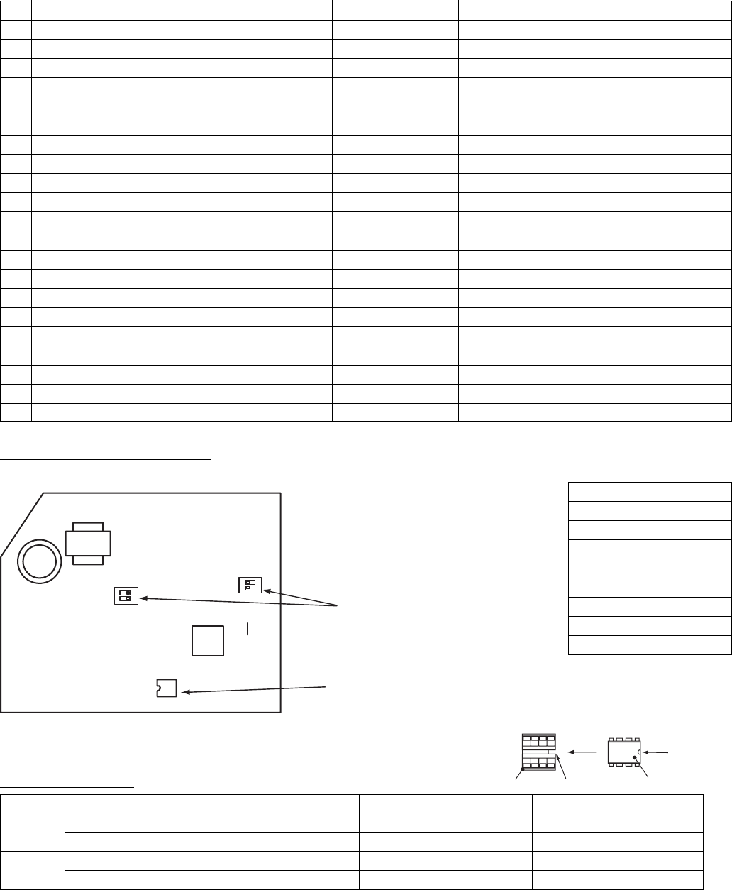
HOW TO REPLACE SERVICE BOARD OF INDOOR UNIT (Continued)
Example of Setting Contents to be Written Down (Code Table)
DN
01
02
03
06
0C
0F
10
11
12
13
14
1E
28
2A
2b
2E
31
32
60
69
8b
Item
Filter sign ON time
Filter contamination level
Central control address
HEAT intake temp. shift
PREPARING indication selection
COOL only
Type
Indoor unit capacity
Refrigerant line address
Indoor unit address
Group address
Temp. range at COOL/HEAT auto switching control
Auto restart after power failure
Option/alarm input (CN80) selection
Thermo output (T10-C) selection
HA terminal (T10-A) selection
Ventilation fan (single operation)
Sensor selection
Timer setting (wired R/C)
Flap setting for cooling
Correction of feeling of strong heating
Memo
Must be set to 0008
Factory setting
0001: 150 hours
0000: Average
0099: Not determined
0002: +2°C
0000: Normal
0000: Heat pump type air conditioner
0008: Wall type
Depends on capacity type
0099: Not determined
0099: Not determined
0099: Not determined
0003: 3°C (Ts±1.5)
0000: Not provided
0002: External alarm input
0000: Thermo output ON
0000: Operation input
0000: Disabled
0000: Unit sensor
0000: Available
0000: Normal
0000: Not provided
Onboard Component Layout
<MCC-1510>
SW01
2
1
ON
1
2
SW02
ON
J01
IC10
DIP switches
(SW01, SW02)
EEPROM (IC10)
Indoor unit capacity
Code “11”
Setting data
0000*
0006
0007
0008
0009
0010
0011
0012
Model
Invalid
40 type
45
50
56
63
71
80
* Default value of EEPROM on the
service board
DIP switch setting
SW01
SW02
Bit 1
Bit 2
Bit 1
Bit 2
Setting
Terminating resistor (for central control)
Selection of R/C A or B
Selection of custom or multiple
Not used
AIK-AP**1H
*1
*1
OFF
OFF
Factory setting
OFF (no resistor)
OFF (A is selected)
OFF (custom models)
OFF
*1: Set to the state before replacement
Mount EEPROM aligning its notch with
the notch of IC socket.
Notch
IC socket Notch EEPROM
– 53 –


