No.
Part name
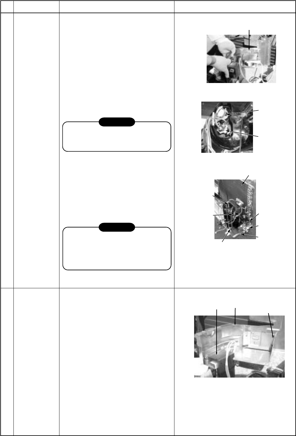
Compressor
Procedure
1) Perform works of items 1 of and
, , , .
2) Discharge refrigerant gas.
3) Remove the partition plate.
(ST1T Ø4 x 10L, 2 pcs.)
4) Remove the noise-insulator.
5) Remove the terminal covers of the
compressor, and disconnect lead
wires of the compressor and the
compressor thermo assembly from
the terminal.
6) Remove pipes connected to the
compressor with a burner.
CAUTION
Pay attention to that flame does not
involve 4-way valve or PMV. (If doing
so, a malfunction may be caused.)
7) Take off the fixing screws of the
bottom plate and heat exchanger.
(ST1T Ø4 x 10L, 2 pcs.)
8) Take off the fixing screws of the valve
clamping plate to the bottom plate.
9) Pull upward he refrigerating cycle.
10) Take off nut fixing the compressor
to the bottom place.
CAUTION
When reconnecting the lead wires to
the compressor terminals after
replacement of the compressor, be
sure to caulk the Faston terminal
without loosening.
Remarks
Reactor 1) Perform works of item 1 of and .
2) First take off two screws (ST1T Ø4 x
10L) of the reactor fixed to the reactor
support.
3) Remove the reactor support from the
partition plate.
(ST1T Ø4 x 10L, 4 pcs.)
4) Take off two screws (ST1T Ø4 x 10L)
directly attached to the partition plate.
Partition plate
Compressor
Case thermo
lead
Heat exchanger
Screw
Valve
support board
Screws (2 pcs.)
Compressor bolt (3 pcs.)
Remove
(Suction pipe)
Remove
(Discharge pipe)
Reactor
Partition
plate
Reactor
support board
– 70 –


