– 43 –
PRE.DFILTERHi POWER
9-10. FINAL INSTALLATION CHECKS
9-10-1. Precautions
Ensure that the electrical cable used for power supply
and control of the system is unable to come into
contact with either service valves or piping work which
are not insulated.
9-10-2. Electrical wiring
When installation is complete, check that all power
supply and interconnecting wiring has been
appropriately protected.
9-10-3. Refrigerant piping
When refrigerant and drain piping have been
completed. Ensure that all pipework is fully insulated
and apply finishing tape to seal the insulation.
9-10-4. Check and Test Operation
• Pressure of R410A is approx. 1.6 times of that of
R22. If installation work is incompletely finished, a
gas leakage may occur at the cases such as
pressure rise during operation.
Therefore, be sure to test the piping connections for
leakage.
• Check the flare nut connections, valve stem cap
connections and service port cap fittings for gas
leak with a leak detector or soap water.
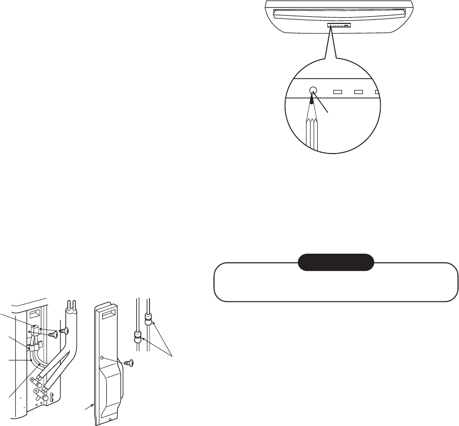
Fig. 9-10-1
Flare nut
connections
(Indoor unit)
Piping cover
Cord clamp
Indoor/Outdoor
connecting
cables
Power cable
Valve cover
9-10-5. Test Operation
To switch the TEST RUN (COOL) mode, press
TEMPORARY button for 10 sec.
(The beeper will make a short beep.)
Fig. 9-10-2
TEMPORARY
button
9-10-6. Auto Restart Setting
This product is designed so that, after a power failure,
it can restart automatically in the same operating
mode as before the power failure.
Information
The product was shipped with Auto Restart
function in the off position. Turn it on as required.
<How to set the Auto Restart>
• Press and hold the TEMPORARY button for about
3 seconds. After 3 seconds, the electronic beeper
makes three short beeps to tell you the Auto Restart
has been selected.
• To cancel the Auto Restart, follow the steps
described in the section Auto Restart Function of
the Owner’s Manual.


