– 31 –
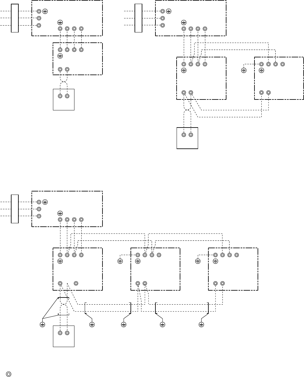
• Single type
Notes)
1. : indicates a terminal block
2. Broken line and chain line indicate wiring at local site.
3. For the inner wiring diagram of the outdoor unit and the indoor unit, refer to the wiring diagram of each model.
4. There is no polarity. It is no problem that the remote controller is connected to the indoor unit terminal block A
and B reversely.
5. When using a wireless remote controller, connection of the remote controller to A and B terminal blocks are
unnecessary. (Wire connection between indoor unit No.1 and No.2 is necessary.)
AB
A
B
123
N
123
L
Outdoor unit
Indoor
unit
Wired remote controller
Wired remote controller
AB
A
B
123
N
123
L
Outdoor unit
Power supply 220-240V
Single phase 50Hz
Power supply 220-240V
Single phase 50Hz
Earth
screw
Indoor unit
No.1 (Header)
AB
123
Indoor unit
No.2 (Follower)
Earth
screw
Earth
screw
Earth
screw
Earth
screw
Earth
screw
Earth
screw
AB
123
Indoor unit
No.3 (Follower)
Wired remote controller
AB
A
B
123
N
123
L
Outdoor unit
Power supply 220-240V
Single phase 50Hz
Earth
screw
Indoor unit
No.1 (Master)
AB
123
Indoor unit
No.2 (Sub)
• Twin type
• Triple type


