


– 84 –
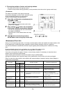
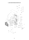
Inverter
assembly
Inverter assembly
Reactor (Partition plate side)
Relay connector
Front cover
Inverter fixing
plate
Case thermo lead
Complessor
lead connector
4way valve
PMV
There is a hook for the
partition board at the rear side.
Wire clamp
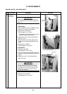
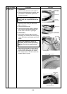
No. Part name Procedure Remarks
f
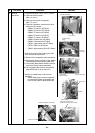
Inverter
assembly
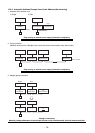
1) Perform works of 1 of c,1 of d ,and e.
2) Remove the front cover.
(M4 x 8, 3 pcs.)
3) Remove the inverter fixing plate.
(M4 x 8, 3 pcs.)
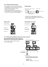
4) Remove connectors connected to other
parts from P.C. board.
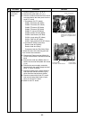
CN601: TD sensor (3P, White)
CN602: TO sensor (2P, Yellow)
CN603: TE sensor (2P, White)
CN604: TS sensor (3P, White)
CN605: TL sensor (2P, White)
CN300: Outdoor fan (3P, White)
CN500: Case thermo (2P, Blue)
CN700: 4-way valve coil (3P, Yellow)
CN701: PMV coil (6P, White)
CN501: High-pressure SW (3P, Green)
*Unlock the locks of the housing part and
then remove the connectors.
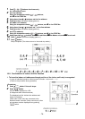
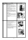
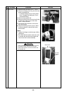
5) Remove the compressor lead connectors.
6) Remove the relay connector of the reactor
lead attached to the partition plate side.
7) Cut bunding band which fixed the various
lead wires to the inverter assembly.
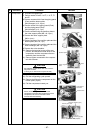
8) Pull up upward the hook for the partition
plate (Back left) so as to remove it.
*Caution for attachment of the inverter
assembly
When attaching the inverter assembly
to the partition plate surely attach the
hook for the partition plate (Back left).