


– 207 –
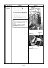
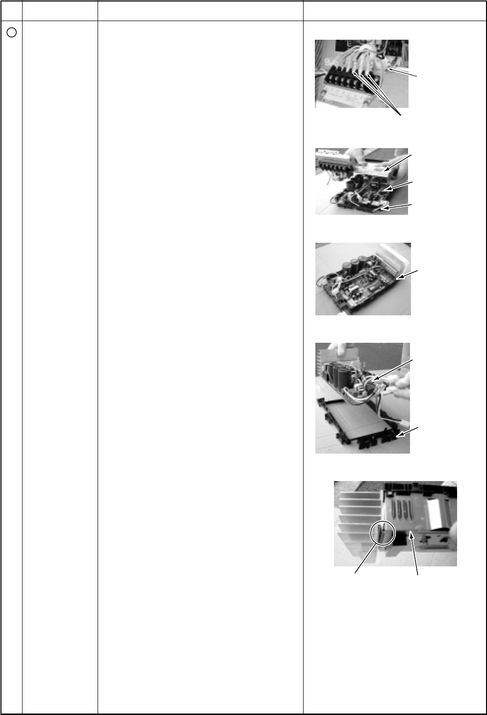
Take off
earth screws.
Power line
Inverter box
(Metal sheet)
Control P.C.
board assembly
P.C. board base
Hooking claws
(4 positions)
Control P.C.
board assembly
P.C. board base
Inverter box
(Metal sheet)
Heat sink
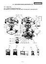
No.
4
Part name
Control P.C.
board assembly
Procedure
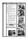
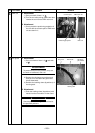
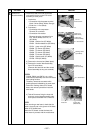
1) Disconnect lead wires and connectors
connected from the control P.C. board
assembly to other parts.
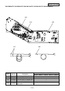
1. Lead wires
• Connection with the power terminal
block: 3 wires (Black, White, Orange)
• Earth wire: 1 wire (Black)
2. Connectors
• Connection with compressor:
Remove 3P connector.
• Connection with reactor:
Remove the relay connectors from
P07, 08 (2P, White) and P12, 13
(2P, Yellow)
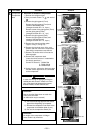
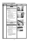
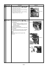
CN300 : Outdoor fan (3P, White)
CN301 : Position detection (5P, White)
CN701 : 4-way valve (3P, Yellow)
CN600 : TE sensor (2P, White)
CN601 : TD sensor (3P, White)
CN603 : TS sensor (3P, White)
CN602 : TO sensor (3P, White)
CN500 : Case thermo. (2P, White)
CN703 : PMV (6P, White)
2) Remove the inverter box (Metal plate).
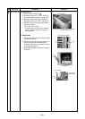
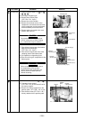
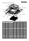
3) Remove the control board assembly
from P.C. board base.
(Remove the heat sink and the control
board assembly as they are screwed.)
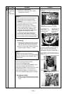
NOTES:
1. CN300, CN301 and CN701, etc. at the
control board assembly side are connectors
with locking function.
Therefore, remove the connector while
pushing the part indicated by an arrow mark.
2. Remove 4 hooking claws of P.C. board
base, and remove upward the heat sink
with hands.
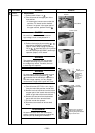
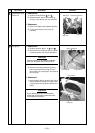
4) Take off 3 screws fixing the heat sink
and main control board assembly side,
and replace the board with a new one.
NOTE:
When mounting a new board, check that the
board is correctly set in the groove of the base
holder of P.C. board base.
Attach the P.C. board so that the heat sink
comes securely contact with the metal sheet.
Remarks