– 45 –
No.
1
2
3
4
5
6
7
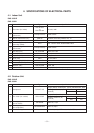
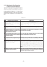
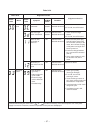
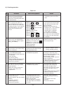
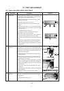
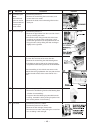
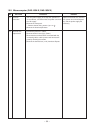
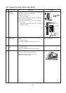
Procedure
Shut off the power supply and
remove the PC board assembly
from the electronic parts base.
Remove the connecting cable from
the terminal block.
Remove the connector for the
motor, and turn the power on.
If the OPERATION lamp flashes
(0.5 sec. :ON, 0.5 sec. :OFF) when
the power turning on, the checking
points described as 1-5 of right
column are not necessary to
perform.
Make the operation status by
pushing once the START/STOP
button, except the status of [FAN
ONLY], [ON TIMER].
Start the operation with the system
which the time of the restart delay
timer is shortened.
Make the operation status by pressing
once the START/STOP button.
1. The time of the restart delay timer
is shortened.
2. Cool operation
3. Air volume [AUTO]
4. Make the setting temperature lower
enough than room temperature.
5. Continuous operation.
The status of No. 5 is continued,
and make the following condition.
1. Heat operation
2. Make the setting temperature
higher enough than room
temperature.
Turn the power on after connecting
the motor connector.
Start the operation with the following
condition.
1. Operation [Cooling]
2. Airflow [High fan]
3. Continuous operation
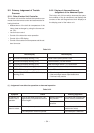
Check Point (Symptom)
1. Is the fuse blown?
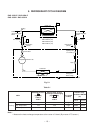
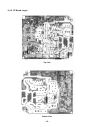
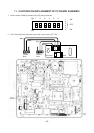
Voltage check
1. Between TP1 and TP2
(220/230/240V AC)
2. Between TP2 and pin 1 of CN04
(220/230/240V AC)
3. Between TP2 and pin 3 of CN04
(220/230/240V AC)
4. Between + and - of C02
(310 ~ 340V DC)
5. Between 35V and GND
6. Between 12V and GND
7. Between 5 V and GND
Voltage check
1. Voltage of relay coil. (DC 12V)
Between pin 10 of IC31 and GND
Between pin 11 of IC31 and GND
2. Between No. 1 and 2 of connecting
cable terminal block.
(220/230/240V AC)
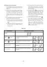
1. All indicators light for 3 sec..
2. Indicators do not indicate normally
after approximate 3 sec..
1. Compressor does not operate.
2. OPERATION lamp flashes.
1. Compressor does not operate.
2. OPERATION lamp flashes.
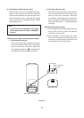
1. The voltage of DC 35V is not
measured between the red and
black of the motor terminals.
2. Motor does not rotate.
(The key operation is accepted.)
3. The motor rotates, but it vibrates
too much.
Causes
1. * Application of shock voltage.
* Overload by short-circuit of the
parts.
1. * AC power cord is defective.
* Poor contact of the terminal plate.
* Miss wiring of the power relay.
2. Fuse is defective.
3. Operation of the thermal fuse.
4. * Capacitor (C01, C15) is defective.
* Line filter (L01) is defective.
* Resistor (R01) is defective.
* Diode (DB01) is defective.
5. IC01, IC02, T01 are defective.
6. IC01, IC02, T01, F03 are defective.
7. IC01, IC02, T01, F02, Q29, IC03
are defective.
1. Breaking wire of the relay coil,
defective relay driver. (IC31)
2. Poor contact of relay.
Defective indicator, or poor
housing assembly. (CN13)
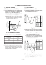
1. The temperature of the indoor heat
exchanger is abnomally lower.
2. Poor contact of the heat exchanger
sensor. (The connector is
disconnected.) (CN01)
3. Heat exchanger sensor, main PC
board are defective.
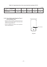
(Refer to Table 9-4-2 for the judgment
of defective resistance values.)
4. Main PC board is defective.
1. The temperature of the heat
exchanger is abnormally high.
2. The heat exchanger sensor
connector has short-circuit. (CN01)
3. The heat exchanger sensor is
defective.
(Refer to Table 9-4-2 for the judgment
of defective resistance values.)
4. PC board is defective.
1. Indoor fan motor is defective.
(Protecting operation on the PC
board.)
2. Poor contact of the motor
connector.
3. PC board is defective.
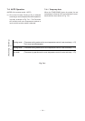
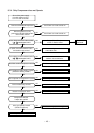
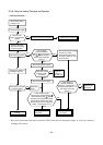
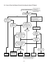
(3) Checking procedure
Table 9-4-1