


– 20 –
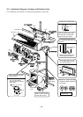
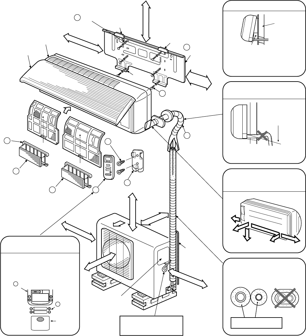
8-2. Installation Diagram of Indoor and Outdoor Units
For installation of the indoor unit, use the paper pattern on the back.
3 Clip anchorClip anchor
Hook
66 mm or more
Hook
1 Installation
plate
8 Mounting screw
Hook
120 mm or more
Front cabinet
Front panel
Air filter
(Attach to the back side.)
(Attach to the back side.)
5 Shield pipe
6 Pan head
wood screw
4 Remote control
holder
2 Wireless
remote
control
9 Deodorizing
filter
10 Purifying
filter
11
Filter
frame
100 mm or more
400 mm or more
Loop the connective cable
(about 100 mm in diameter
and 300~350 mm long).
600 mm or more
Electric parts
cover
45 mm or more
600 mm or more
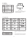
2
Wireless remote control
7
Batteries
Cover
6 mm thick heat resisting
polyethylene foam
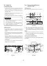
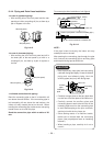
Bottom
Rear
Right
Rear left
Left
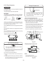
Cut the piping hole
sloped slightly
Wall
120 mm
or more
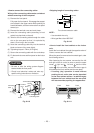
For the rear and left piping
Insert the remote control holder
cushion between the indoor
unit and wall, and lift indoor
unit to make work easier.
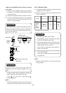
Do not allow the drain hose to
get slack.
Make sure to run the drain
hose sloped downward.
The auxiliary piping can be
connected the left, rear left,
rear, right or bottom.
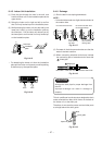
Insulation of refrigerant pipes
insulates the pipes separately,
not together.
Before install the wireless
remote control
• With the remote control cover
open, load the batteries
supplied correctly, observing
their polarity.
Extension
drain hose
(Option:
RB-821SW)