


FILE NO. SVM-07008
– 85 –
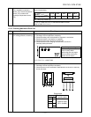
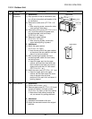
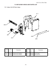
No. Part name Procedures Remarks
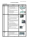
1) Disconnect lead wires and connectors
connected from the control board
assembly to other parts.
1. Lead wires
• Connection with terminal block :
3 wires (Black, White, Orange)
• Connection with compressor : remove
the connector (3P)
• Connection with reactor : remove the
connector (2P)
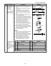
2. Connectors (6 positions)
CN300, CN703 : Outdoor fan (3P: white)*
(See Note 1)
CN701 : 4 way valve (3P: Yellow)*
CN601 : TD sensor (2P: White)
CN602 : TO sensor (2P: White)
CN500 : Case thermo (2P: White)
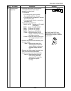
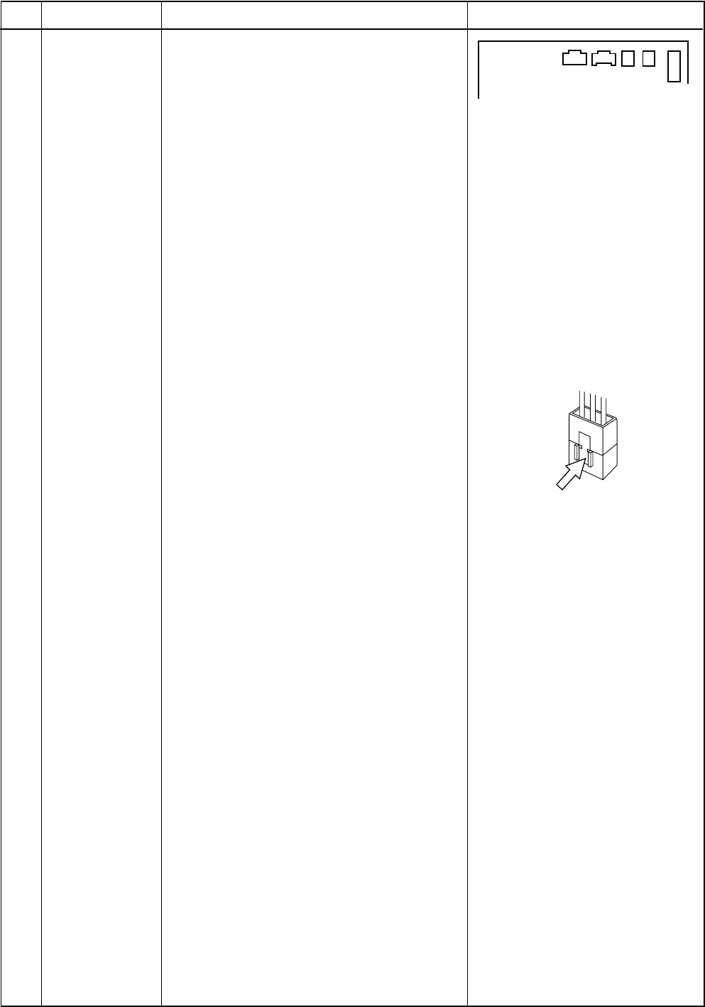
∗ Note 1) As the connector has a
stopper, release the housing
lock when removing.
∗∗Note 2) Hold the housing (resin part)
with stopper and pull out to
remove.
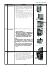
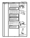
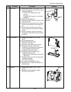
2) Remove the control board assembly from
the inver ter box.
Note 2) Remove the claw of the
board support fixed to the
inverter board, and remove
upwards holding the heat
sink.
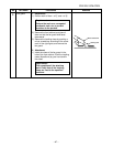
3) Remove the three screws fixing the heat
sink and control board assemble.
4) Attach the new contro board assembly.
Note 4) When attaching the new
control board assembly.
insert the P.C. board into
the guide rail groove
correctly.
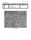
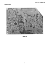
4 Control board
assembly
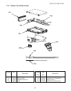
CN300 CN701
CN602
CN601
CN500
As CN300 and CN701 are
connectors with lock, remove
while pushing the part indicated
by an arrow