


4
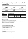
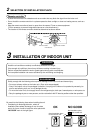
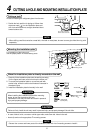
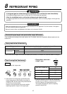
Installation space
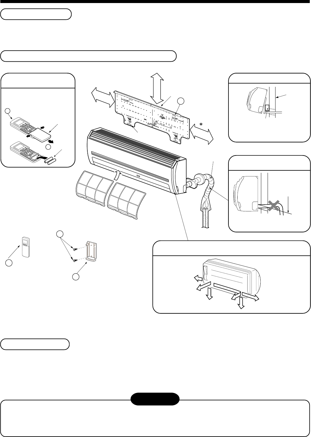
Reserve space required to install the indoor unit and for service work.
Keep 100mm or more for clearance between top plate of the indoor unit and the ceiling surface.
Installation diagram of Indoor and outdoor units
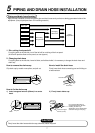
The auxiliary piping can be connected the left, rear left, rear right,
right, bottom right or bottom left.
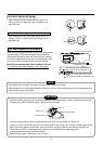
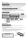
Before installing the
wireless remote controller
• With the remote controller cover
open, load the batteries supplied
correctly, observeing their polarity.
2 Wireless remote controller
3 Batteries
Cover
2
Wireless
remote controller
4
Remote control holder
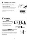
Do not allow the drain hose to
get slack
Cut the piping hole
sloped slightly
Make sure to run the drain hose
sloped downward.
Left
Rear left
Right
Rear right
Bottom right
For the rear left and left piping
Wall
Insert the cushion between the
indoor unit and wall, and tilt the
indoor unit for better operation.
Bottom left
6
Pan head wood screw
Hook
170mm
or more
170mm
or more
100 mm or more
Hook
1
Installation
plate
Air filter
(Attach to the front panel)
Shield pipe
∗ When installing the Flow Selector Unit (FS Unit),
keep a space more than 300mm for wiring work.
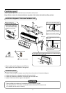
Installation place
• A place which provides the spaces around the indoor unit as shown in the above diagram.
• A place where there is no obstacle near the air inlet and outlet.
• A place that allows easy installation of the piping to the outdoor unit.
• A place which allows the front panel to be opened.
CAUTION
• Direct sunlight to the indoor unit’ s wireless receiver should be avoided.
• The microprocessor in the indoor unit should not be too close to RF noise sources.
(For details, see the owner’ s manual.)