


13
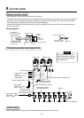
Indoor unit power supply (*1)
• For the power supply of the indoor unit, prepare the exclusive power supply separated from that of the outdoor unit.
• Arrange the power supply, earth leakage breaker, and main switch of the indoor unit connected to the same
outdoor unit so that they are commonly used.
• Power supply cord specification : Cable 3-core 2.5mm², in conformity with Design 60245 IEC 57.
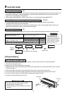
Indoor/Outdoor inter-unit wiring, Central controller wiring (*2) (*3)
• 2-core with polarity wires are used for the Indoor/Outdoor inter-unit wiring and Central controller wiring.
• To prevent noise trouble, use 2-core shield wire.
• The length of the communication line means the total length of the inter-unit wire length between indoor and
outdoor units added with the central control system wire length.
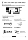
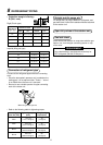
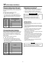
Remote controller wiring (*4)
• 2-core with non-polarity wire is used for wiring of the remote controller wiring and group remote controllers wiring.
Twist wire: 0.5mm
2
to 2.0mm
2
× 2
Total wire length of remote controller
wiring and remote controller inter-unit
wiring = L + L1 + L2 + … Ln
In case of wired type only
In case of wireless type included
Remote controller wiring, remote
controller inter-unit wiring
CAUTION
The remote controller wire
(Communication line) and
AC220–240V wires cannot be
parallel to contact each other and
cannot be stored in the same
conduits. If doing so, a trouble
may be caused on the control
system due to noise, etc.
Total wire length of remote controller inter-unit wiring = L1 + L2 + … Ln
Up to 500m
Up to 400m
Up to 200m
Remote controller inter-unit wiring
Indoor unit
Remote
controller
Indoor unit
L1 L2 Ln
(Max. 8 units)
Indoor unit Indoor unit
Remote
controller
wiring
9
ELECTRIC WORK
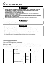
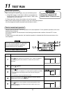
Wiring connection
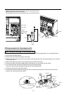
How to connect the power cable
For the air conditioner that does not have power cable, connect a power cable to it as mentioned below.
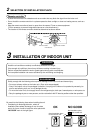
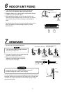
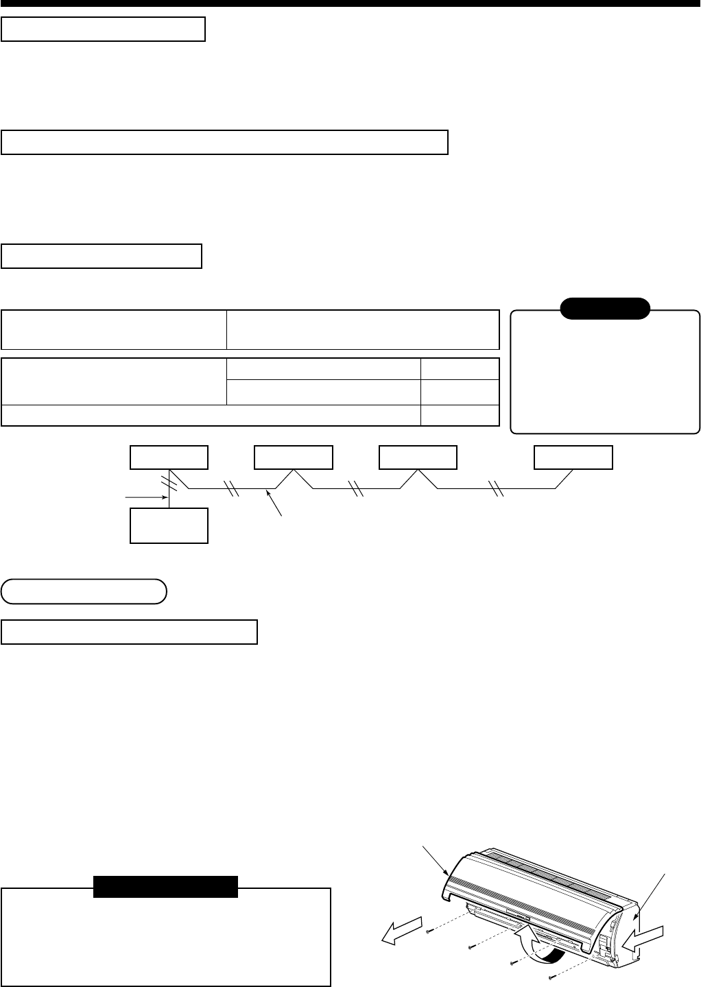
1. Open the air inlet grille upward.
2. Remove the four screws securing the front panel.
3. Slightly open the lower part of the front panel then pull the upper part of the front panel toward you to remove it
from the rear plate.
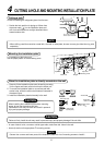
4. After removing the front panel, remove the power cable connect cover and the cord clamp.
5. Connect and secure the power supply cable and secure the cord clamp and the power connect cover.
6. Cut the slit and front panel, and put the power supply cable through the notch.
7. Be sure to smooth the notch with a file, etc.
3
1
2
Air inlet grille
Front panel
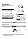
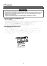
REQUIREMENT
• Be sure to pass the cable through the cable
connection port of the indoor unit.
• The low-voltage circuit is provided for the remote
controller.