


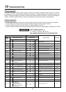
17
Change of lighting time of filter sign
According to the installation condition, the lighting time
of the filter sign (Notification of filter cleaning) can be
changed.
Follow to the basic operation procedure
(
1
→
2
→
3
→
4
→
5
→
6
).
• For the item code in Procedure
3
, specify [01].
• For the [Set data] in Procedure
4
, select the setup
data of filter sign lighting time from the following
table.
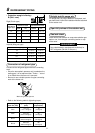
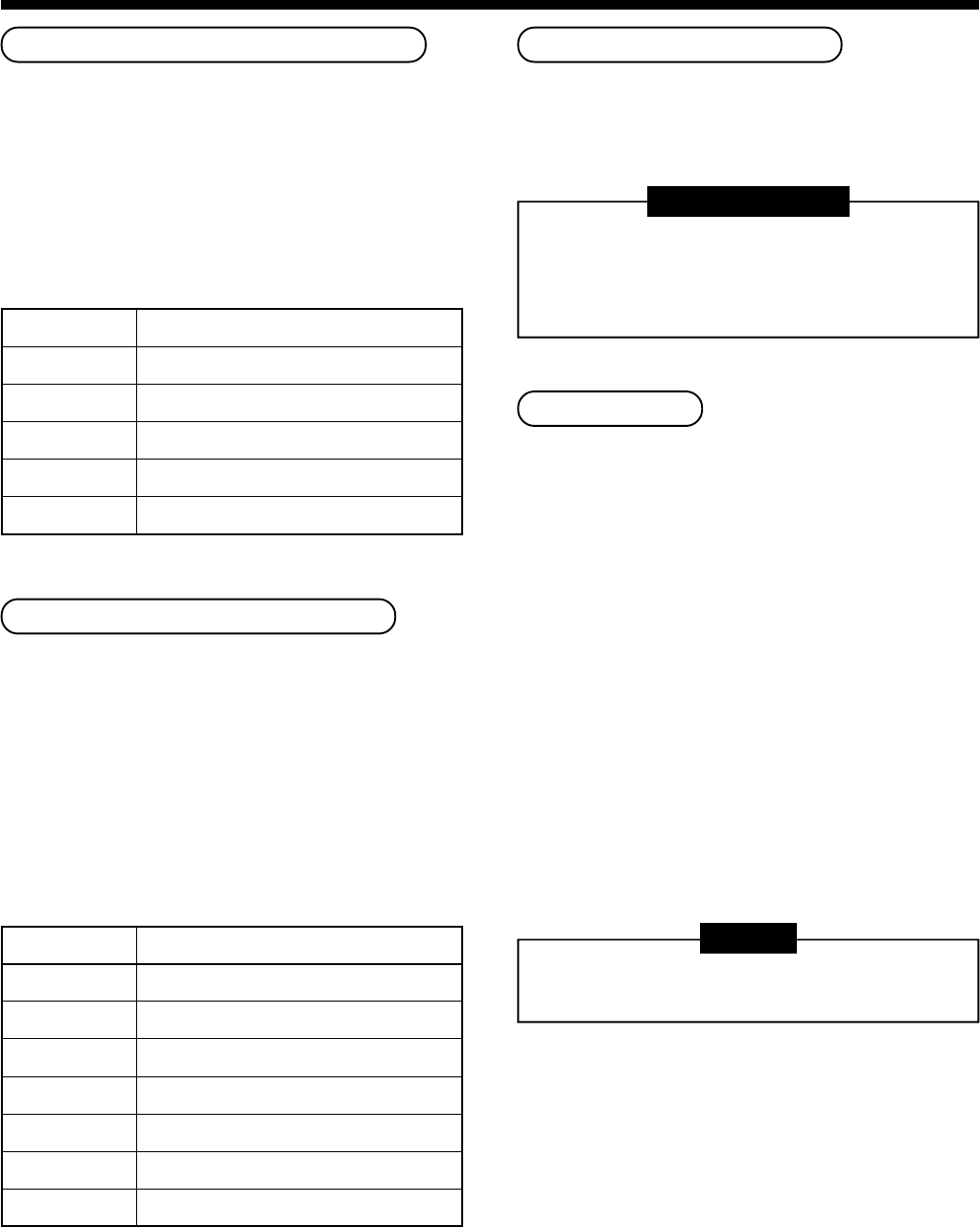
Setup data
0000
0001
0002
0003
0004
Filter sign lighting time
None
150H (At shipment from factory)
2500H
5000H
10000H
To secure better effect of heating
When it is difficult to obtain satisfactory heating due to
installation place of the indoor unit or structure of the
room, the detection temperature of heating can be
raised. Also use a circulator, etc. to circulate heat air
near the ceiling.
Follow to the basic operation procedure
(
1
→
2
→
3
→
4
→
5
→
6
).
• For the item code in Procedure
3
, specify [06].
• For the set data in Procedure
4
, select the setup
data of shift value of detection temperature to be set
up from the table below.
Setup data
0000
0001
0002
0003
0004
0005
0006
Detection temp shift value
No shift
+1°C
+2°C (At shipment from factory)
+3°C
+4°C
+5°C
+6°C
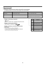
Adjustment of air direction
1. Using the remote controller switch, change the up/
down air direction by moving the horizontal flap.
2. Adjust the right/left air direction by bending the
vertical grille inside of the air outlet port with hands.
REQUIREMENT
Do not touch the horizontal flap directly with
hands; otherwise a trouble may be caused.
For handling of the horizontal flap, refer to
“Owner’s Manual” attached to the outdoor unit.
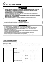
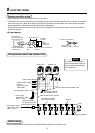
Group control
In a group control, a remote controller can control up
to maximum 8 units.
• The wired remote controller only can control a group
control. The wireless remote controller is unavailable
for this control.
• For cabling procedure and cables of the individual
line (Identical refrigerant line) system, refer to
“Electric work” in this Manual.
• Cabling between indoor units in a group is performed
in the following procedure.
Connect the indoor units by connecting the remote
controller inter-unit cables from the remote controller
terminal blocks (A, B) of the indoor unit connected
with a remote controller to the remote controller
terminal blocks (A, B) of the other indoor unit.
(No polarity)
• For address setup, refer to the Installation Manual
attached to the outdoor unit.
NOTE
Net work adapter (Model TCB-PCNT20E) can not
connect to this High Wall type air conditioner.
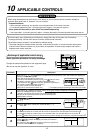
10
APPLICABLE CONTROLS