


15
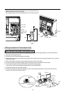
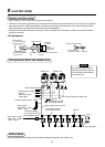
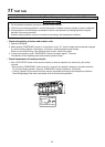
Remote controller wiring
• Strip off approx. 14mm cover of the wire to be connected.
• Twist wire of the remote controller to be connected with wire of the remote controller unit (or sensor), and press-fit
them with a wire joint. (Wire joints (White: 2 pieces) are included in the accessory of the main remote controller
(sold separately) or wireless remote controller kit (sold separately).)
• As the remote controller wire has no polarity, there is no problem if connections to indoor unit terminal blocks A
and B are reversed.
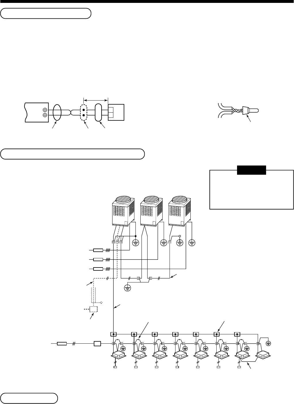
<Wiring diagram>
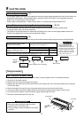
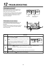
Wiring between indoor and outdoor units
NOTE
An outdoor unit connected
with indoor/outdoor inter-unit
wire becomes automatically
the header unit.
Address setup
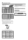
Set up the addresses according to the Installation Manual attached to the outdoor unit.
Terminal block
for remote controller
wiring of indoor unit
A
B
Approx. 200mm
W : White
B : Black
W
B
Remote controller wire
(Local procure)
Wire from remote controller unit
or sensor
Connecting
part
Remote
controller unit
or sensor part
Wire from remote
controller or sensor
Remote controller wiring
Wire joint
Header unit Follower unit
Earth leakage breaker
Earth leakage breaker
Switch
(Earth)
(Open)
Earth
Outdoor power supply
3-phase
380–415V, 50Hz
380V, 60Hz
Central control line wire
Power supply
220–240V
~
50Hz
220V
~
60Hz
Remote controller,
for central control, etc.
Connection of shield
wire closed terminal
Inter-unit wire between outdoor units
Indoor/Outdoor inter-unit wire
Indoor power supply
220–240V
~
50Hz
220V
~
60Hz
(Earth)
Connection of shield
wire closed terminal
(Remote controller group operation)
Pull box
Indoor unit
9
ELECTRIC WORK