Form RZ-NA I-UDA, P/N 195673 Rev 5, Page 36
FOR SERVICE OR REPAIR, FOLLOW THESE STEPS IN ORDER:
FIRST: Contact the Installer
Name __________________________________________________________
Address_________________________________________________________
__________________________________________________________
__________________________________________________________
Phone _____________________________________
SECOND: Contact the nearest distributor (See Yellow Pages). If no listing,
contact Authorized Factory Representative, 1-800-695-1901 (Press 1).
THIRD: Contact REZNOR
®
/ Thomas & Betts Corporation
150 McKinley Avenue
Mercer, PA 16137
Phone: (724) 662-4400
Date of
Model No. ______________Unit Serial No._____________________________ Installation _______________
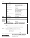
40. Troubleshooting (cont’d)
(800) 695-1901; www.ReznorOnLine.com
©2003 Thomas & Betts Corporation, All rights reserved. Printed in the U.S.A.
MANUFACTURER OF HEATING, COOLING, AND VENTILATING SYSTEMS
Trademark Note: Reznor
®
, TCORE
2®
, and are trademarks of Thomas & Betts.
1/03 YL Form RZ-NA I-UDA (Version .5)
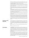
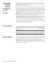
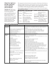
PROBLEM (cont’d) PROBABLE CAUSE (cont’d) REMEDY (cont’d)
Burner will not light
(cont’d)
10. Integrated circuit board does not power
main valve.
10.
a) Loose wire connections. a) Check and tighten all wiring connections.
b) Flame sensor grounded. b) Be certain flame sensor lead is not grounded or insulation or
ceramic is not cracked. Replace as required.
c) Incorrect gas pressure. c) Supply pressure should be 5" - 14" w.c. for natural gas or 11" - 14"
w.c. for propane gas.
d) Cracked ceramic at sensor. d) Replace sensor.
1. Gas pressure too high or too low. 1. Supply pressure should be 5" - 14" w.c. for natural gas or 11" - 14"
w.c. for propane gas.
2. Burner not grounded 2. Make certain integrated circuit board is grounded to ignitor.
3. Circuit board not grounded. 3. Make certain integrated circuit board is grounded to furnace chassis.
4. Faulty integrated circuit board 4. If 24 volt is available to the integrated circuit board and all other
causes have been eliminated, replace board.
5. Combustion air proving switch 5.
not closing. a) Make sure unit is properly vented.
b) Remove obstructions from vent.
c) Replace faulty tubing to pressure switch.
6. Faulty combustion air proving switch. 6. Replace combustion air proving switch.
7. Flame sensor grounded. 7. Be certain flame sensor lead is not grounded or insulation or ceramic
is not cracked. Replace as required.
8. Cracked ceramic at sensor. 8. Replace sensor.
9. Incorrect polarity. 9. Reverse line volt leads to integrated circuit board.
1. Incorrect valve outlet pressure or orifice. 1. Check valve outlet pressure. See Rating plate for manifold pressure.
2. Cycling on limit control. 2. Check air throughput.
3. Improper thermostat location or adjustment. 3. See thermostat manufacturer’s instructions.
1. Circuit o
p
en. 1. Check wirin
g
and connections.
2. Defective integrated circuit board. 2. Replace board.
3. Defective motor or starter. 3. Replace motor or starter.
Fan or venter motor
turns on and off while
burner is o
p
eratin
g
1. Motor overload device cycling on and off. 1. Check motor load against motor rating plate. Replace motor if
needed.
1. Low or high voltage supply. 1. Correct electric supply.
2. Defective motor. 2. Replace motor.
3. Poor air flow. 3. Clean motor, fan, fan guard, filter, and coils.
4. Defective bearing or lubrication. 4. Lubricate bearings (motor permitting) or replace motor.
Fan or venter motor cuts
out on overload
No heat (Heater
Operating)
Fan or venter motor will
not run
Burner cycle on and off


