


Form RZ-NA I-UDA, P/N 195673 Rev 5, Page 30
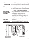
Instructions to Re-Install the Burner (Refer to FIGURE 17)
1. Attach the Burner Assembly - Holding the venturi tube, slide the entire
burner assembly into position. Align the supports on the left side with the
slots in the burner shield; sliding the supports into the slots. On the right, re-
attach each burner body support to the secondary air shield.
2. Attach the Secondary Air Baffles (Sizes 60-400 only) - Re-attach the
secondary air baffles as marked. Baffles may be different sizes and each
must be attached in the correct location.
3. Attach the Control Assembly - Carefully slide the control assembly into
position. Re-attach with the same screws. Check to be sure all wire connec-
tions are secure.
4. Attach the Gas Train - Slide the gas train so that the orifice adapter is
through the bracket. Fasten the gas train to the bracket with the locking nut.
Install the gas orifice. Re-connect the wires to the gas valve.
5. Close the access panel.
6. Reconnect the gas supply at the union outside of the cabinet. Leak test the
connection with leak detecting solution.
7. Turn on the electric and the gas. Check for proper operation.
28. Burner
Orifice
Burner orifice usually only needs to be replaced when installing a gas conversion
kit. If ordering a replacement orifice only, give BTUH content and specific grav-
ity of gas, as well as the model and serial number of the unit. When removing or
replacing the burner orifice be careful not to damage the venturi tube and/or the
bracket.
Re-Install the Burner
size. Each baffle is held in place by one screw. For re-assembly, on the
secondary air shield, mark the location (top and bottom) of each baffle.
Remove all baffles.
8. Remove Burner Assembly
a) Locate the burner body supports. Depending on the size, the burner will
have two or more supports. At each support, remove the one screw that
attaches it to the secondary air shield
b) Holding the venturi tube, slide the entire burner assembly slightly to the
right to disengage the burner from the supports on the left. Then rotate
the open end of the venturi tube inward toward the heater. Carefully pull
the burner assembly out of the cabinet.
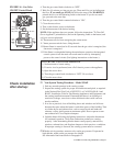
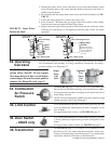
With the burner assembly removed, shine a flashlight on the burner ribbons. Look
for carbon buildup, scale, dust, lint, and/or anything that might restrict flow through
the spaces between the burner ribbons. Holding the burner assembly so that any
foreign material will fall away from the burner, use a stiff bristle brush to loosen
and remove any foreign material(s). If the burner is excessively dirty, remove one
of the burner end caps. Remove the four screws that hold the end cap to the burner
housing. Lightly tap the end cap to remove it.
Clean all foreign material from the burner and venturi. After the burner is thor-
oughly clean, replace the end cap making certain that it is tight against the burner
housing. NOTE: If any of the burner components are damaged or deteriorated,
replace the burner assembly.
Inspect the Lower Portion of the Heat Exchanger (with burner
assembly removed)
At the burner flame entrance of each tube, shine a bright light into each heat
exchanger section. With the light shining into the heat exchanger, observe the
outside for visible light. Repeat this procedure with each heat exchanger section.
If any light is observed, replace the heat exchanger.
27. Burner
Maintenance
(cont’d)
Burner Removal
(cont’d)
Inspect and Clean the
Burner