


Form RZ-NA I-UDA, P/N 195673 Rev 5, Page 14
12. Gas Piping
and
Pressures
(cont’d)
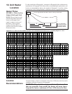
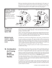
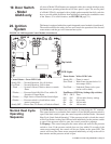
2. Locate the 1/8” output pressure tap on the valve (See FIGURE 11). Turn the
knob on the top of the valve to “OFF”. Connect a manometer to the 1/8" pipe
outlet pressure tap in the valve. Use a water column manometer that is readable
to the nearest tenth of an inch.
3. Single Stage and Two Stage High Fire - Turn the knob on the top of the valve
to “ON”. Remove the cap from the pressure adjusting screw and adjust the gas
train pressure to the pressure selected from the table above. Adjust pressure by
turning the regulator screw IN (clockwise) to increase pressure or OUT (coun-
terclockwise) to decrease pressure.
Two Stage Low Fire - Disconnect the wire from the “HI” terminal on the gas
valve and check the low fire pressure. Turn the regulator screw to adjust the
low fire outlet pressure to the “Low Fire” pressure selected from the table. Re-
connect the wire to the gas valve.
4. Turn up the thermostat. (NOTE: On Model UDAS, depress and hold the door
safety switch.) Cycle the burner once or twice to properly seat the adjustment
spring in the valve.
Re-check the pressure(s). When the outlet pressure is right for the installation,
remove the manometer and replace the cap.
Check for leak at the pressure tap fitting.
5. With the heater operating determine that the inlet pressure to the heater for
natural gas is between 5 and 13.5 inches w.c. and for propane between 10 and
13.5 inches w.c. Take this reading as close as possible to the heater (Heaters are
equipped with gas valves that have an inlet pressure tap.) If the inlet pressure is
not within the specified range, the inlet pressure must be corrected and Steps 3
and 4 repeated.
6. Find the High Altitude Adjustment label in the plastic bag that contained these
instructions. Using a permanent marker, fill-in the appropriate information from
the tables on page 15. Select a location for the label on the outside of the heater
access panel so that it will be conspicuous to anyone operating or servicing the
unit. Be sure the surface is clean and dry and adhere the label.
Derate by Valve
Outlet Pressure
Adjustment for High
Altitude Operation
Instructions for High Altitude Derate
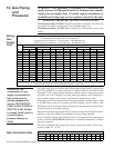
1. Determine the required valve outlet pressure for the elevation where the heater
will be operating. If unsure of the elevation, contact the local gas supplier.
Valve Outlet Pressure Settings by Elevation
This adjustment can only
be done after the heater is
in operation. It is included
in the startup procedures.
NOTE: If elevation is
above 6000 ft (1830M), a
high altitude pressure
switch is required; see
Paragraph 7.
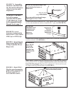
FIGURE 11 - Top View of
Valves showing Outlet
Pressure Tap and
Adjustment Locations
Single-Stage Valve
1/8” Output
Pressure
Tap
Adjust Low
Pressure
Output
Adjust High
Pressure
Output
1/8” Output
Pressure Tap
Inlet
Pressure
Tap
Inlet
Pressure
Tap
Two -Stage Valve
Output
Adjustment
Screw
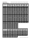
Feet Meters
Single Stage and
Two Stage High Fire
Two Stage
Low Fire
Single Stage and
Two Stage High Fire
Two Stage
Low Fire
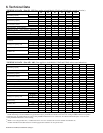
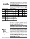
0-2000 0-610 3.5 1.8 10.0 5.0
2001-3000 611-915 3.1 1.6 8.8 4.4
3001-4000 916-1220 3.0 1.5 8.5 4.2
4001-5000 1221-1525 2.8 1.5 8.1 4.1
5001-6000 1526-1830 2.7 1.4 7.7 3.9
6001-7000 1831-2135 2.6 1.3 7.4 3.7
7001-8000 2136-2440 2.5 1.3 7.1 3.5
8001-9000 2441-2745 2.4 1.2 6.7 3.4
9001-10000 2746-3045 2.3 1.2 6.7 3.4
Feet Meters
Single Stage and
Two Stage High Fire
Two Stage
Low Fire
Single Stage and
Two Stage High Fire
Two Stage
Low Fire
0-2000 0-610 3.5 1.8 10.0 5.0
2001-4500 611-1373 2.8 1.5 8.1 4.1
Manifold Pressure Settin
g
s b
y
Altitude for the UNITED STATES
Manifold Pressure Settin
g
s b
y
Altitude for CANADA
Altitude Natural Gas (inches w.c.) Propane Gas (inches w.c.)
Altitude Natural Gas (inches w.c.) Propane Gas (inches w.c.)