


Form RZ-NA I-UDA, Mfg #195673 Rev 5, Page 31
29. Ignition
System
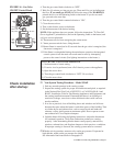
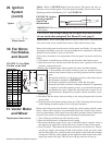
DSI Integrated Control Module (circuit board) - See FIGURE 19. The module
monitors the operation of the heater including ignition. The only replaceable com-
ponent is the 3 amp Type ATC or ATO fuse. If the fuse is blown, the problem is
most likely an external overload. Correct the problem and replace the fuse.
Do not attempt to disassemble the control module. However, each heating season
check the lead wires for insulation deterioration and good connections.
Proper operation of the direct spark ignition system requires a minimum flame
signal of 1.0 microamps as measured by a microampmeter.
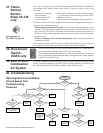
For further information and check out procedure on the direct spark ignition sys-
tem, refer to Paragraph 20 and the Troubleshooting Flow Chart in Paragraph 40.
FIGURE 19 - DSI
Integrated Control Module
(Circuit Board)
Only replaceable part
is a Type ATC or ATO 3
amp fuse (Color Code
Violet), P/N 201685
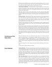
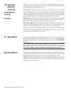
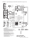
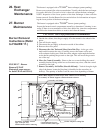
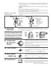
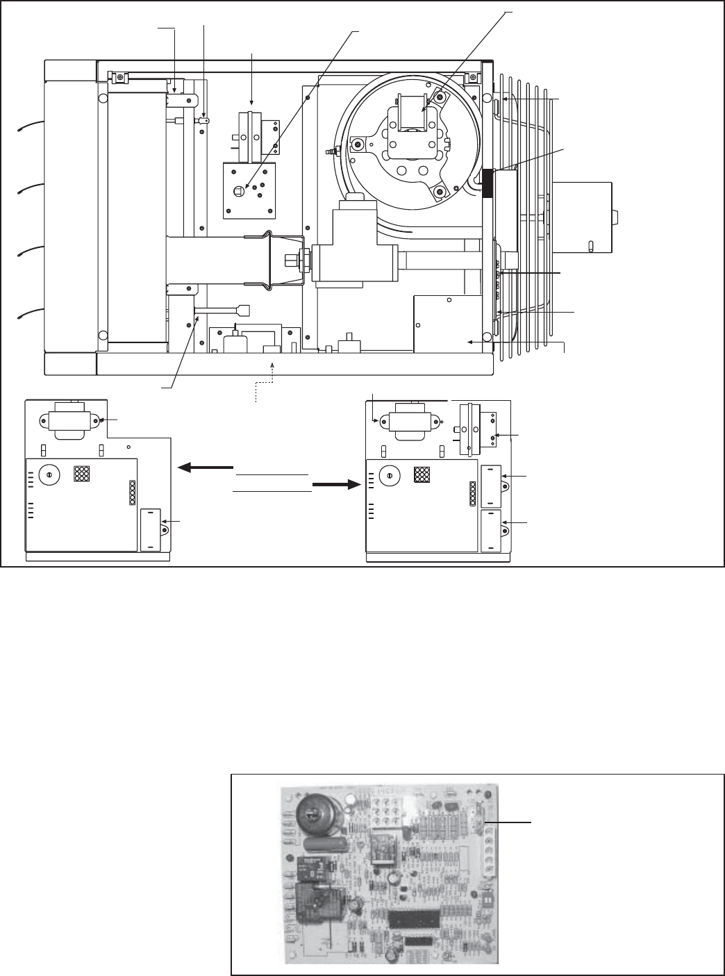
FIGURE 18 - Location of Controls
Pressure Switch
- Sizes 30-125
Venter Motor (Size 30-75
illustrated. Venter motor
is in the same location for
all models, but appear-
ance is different.)
Fan
Motor
Gas Valve
Transformer
Circuit Board
(DSI Integrated
Control Module)
Optional
Fan Motor
Capacitor
High Temperature
Limit Control
Flame Rollout Switch
(Sizes 30-125)
Ignitor
Flame Sensor
Burner Assembly
Terminal
Board (24V)
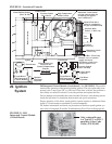
Transformer
Circuit Board
(DSI Integrated
Control Module)
Fan Motor
Capacitor
Venter Motor
Capacitor
Pressure Switch
(Sizes 150-400)
Control Panel Assy
located on the
Control Compartment
Bottom
Sizes 30-125
Sizes 150-400
Model UDAS has a
collar for combustion
air pipe (not illustrated)
Interlock Door
Switch - UDAS only
Electrical Box - UDAS only
Remove cover to connect
supply and access
disconnect switch wires .
Always replace cover.
Disconnect Switch
- UDAS only