Form RZ-NA I-UDA, Mfg #195673 Rev 5, Page 33
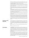
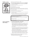
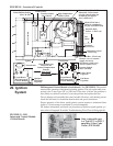
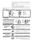
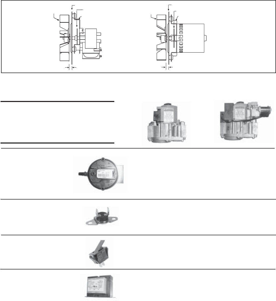
FIGURE 22 - Venter Wheel
Position on Shaft
5/16” (8mm) inside
5/16” (8mm) inside
Venter Wheel,
Sizes 30-75
Venter Motor Plate
Fan
Motor Mounting
Bracket
Motor Sizes
100-400
Venter Wheel,
Sizes 100-175*
Venter Motor Plate
Motor Mounting Bracket
Fan
*Venter wheel has
different appearance
on Sizes 200-400.
Motor spacing is
the same.
Motor
Sizes
30-75
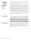
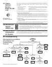
32. Operating
Gas Valve
Single
Stage
Gas
Valve
Optional
Two
Stage
Gas
Valve
33. Combustion
Air Pressure
Switch
See FIGURE 18, page 31, for location. If it is determined that
the pressure switch needs replacing, use only the factory-autho-
rized replacement part that is designed for the model and size of
heater being serviced.
NOTE: A unit operating above 6000 ft elevation requires a high
altitude pressure switch. See Paragraph 7.
34. Limit Control
If it is determined that the limit control needs replacing, use only
a factory-authorized replacement part that is designed for the
size of heater.
For approximate limit location, see FIGURE 18, page 31.
35. Door Switch
- UDAS only
If it is determined that the door switch needs replacing, use only
a factory-authorized replacement part that is designed for the
heater.
For approximate switch location, see FIGURE 18, page 31.
WARNING: The operating valve is the
prime safety shutoff. All gas supply
lines must be free of dirt or scale before
connecting to the unit to ensure positive
closure. See Hazard Levels, page 2.
36. Transformer
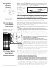
See FIGURE 18, page 31, for location. Use a voltmeter to verify
that there are 24 volts output from the transformer. If the trans-
former is not functioning, it must be replaced. Use a replacement
transformer identical to the factory-installed model.
The gas valve requires no field maintenance except careful removal of external
dirt accumulation and checking of wiring connections. Instructions for testing
pressure settings re in Paragraph 12.
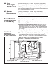
5. Holding the venter motor, remove the three or four screws that attach the venter
motor mounting plate to the venter housing. Remove the motor and wheel as-
sembly from the heater.
6. Re-assemble with the replacement venter motor and wheel assembly. See FIG-
URE 22.
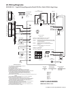
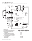
7. Follow the wiring diagram to connect the venter wires.
8. Sizes 30 and 45 - Reconnect the gas supply at the union outside of the cabinet.
Leak test the connection with leak detecting solution.
9. Replace the access panel. Restore power to the heater and turn on the gas. Light,
following the instructions on the lighting instruction plate. Check for proper
operation.


